

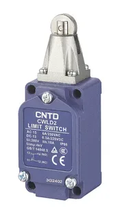


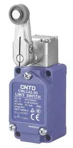


| Part Number: | CWL | D | - | P |
|---|---|---|---|---|
| Explanation: |
Series CWL - Cast aluminum vertical limit switch series |
Actuator D - Top plunger |
Cable entry NONE - One M20 cable entry; omit P and the preceding hyphen |
CWL limit switches combine a cast aluminum enclosure, IP66 protection and a double-spring snap-action 1NO+1NC contact mechanism. The range includes direct plungers, fixed and adjustable rotary levers, flexible spring heads and four latching fork configurations. Fork models retain their changed contact state until the actuator is driven back from the opposite direction.
| Model | Actuator | Key dimensions |
|---|---|---|
| CWLD | Top plunger | Ø9mm plunger |
| CWLD1 | Vertical roller plunger | Ø17×5mm roller |
| CWLD2 | Transverse roller plunger | |
| CWLD3 | Ball plunger | Ø15.5mm head |
| CWLCA2-2 | Fixed metal roller lever | Ø18×6.3mm roller; radius 38mm |
| CWLCA2-2G | Fixed plastic roller lever | |
| CWLCL | Adjustable rod lever | Ø3±0.2mm rod; adjustable projection 25–140mm |
| CWLCA12-2-Q | Adjustable metal roller lever | Ø17.5×7mm roller; radius 25–89mm |
| CWLCA12-2-QG | Adjustable plastic roller lever | |
| CWLCA12-2-QD | Adjustable large rubber roller lever | Ø50×8mm roller; radius 42–89mm |
| CWLCA32-41 | Latching fork; plastic rollers on opposite faces | Two Ø17.5×7mm rollers; radius 38mm; fork angle 90±3° |
| CWLCA32-41M | Latching fork; metal rollers on opposite faces | |
| CWLCA32-42 | Latching fork; plastic rollers on the same face | |
| CWLCA32-42M | Latching fork; metal rollers on the same face | |
| CWLNJ | Coil spring | Ø6.5mm spring |
| CWLNJ-30 | Metal rod coil spring | Ø6.5mm metal tip; tip length 57.2mm |
| CWLNJ-2 | Plastic rod coil spring | Ø3.2mm plastic tip; tip length 37.8mm |
| CWLNJ-S2 | Flexible whisker | Ø1.2mm tip; tip length 52.5mm |
Flexible-head height is 140±2.5mm. Body width is approximately 40mm, with model-specific depth and mounting-hole details in the drawings. The standard entry is M20, with M20×1.5 specified in the corresponding drawings. Optional suffix -P selects one PG13.5 entry.
The code combines CWL with one complete actuator token. For example, CWLD-P selects the top plunger and a PG13.5 entry. Keep internal characters of actuator tokens intact: CA12-2-QG and NJ-S2 each identify a complete actuator. Only the final -P is the optional cable-entry suffix; omit it for M20.
| Segment | Code | Meaning |
|---|---|---|
| Series | CWL | Cast aluminum limit switch family |
| Actuator | D | Top plunger |
| D1 | Vertical roller plunger | |
| D2 | Transverse roller plunger | |
| D3 | Ball plunger | |
| CA2-2 | Fixed metal roller lever | |
| CA2-2G | Fixed plastic roller lever | |
| CL | Adjustable rod lever | |
| CA12-2-Q | Adjustable metal roller lever | |
| CA12-2-QG | Adjustable plastic roller lever | |
| CA12-2-QD | Adjustable large rubber roller lever | |
| CA32-41 | Latching fork, plastic rollers on opposite faces | |
| CA32-41M | Latching fork, metal rollers on opposite faces | |
| CA32-42 | Latching fork, plastic rollers on the same face | |
| CA32-42M | Latching fork, metal rollers on the same face | |
| NJ | Coil spring | |
| NJ-30 | Metal rod coil spring | |
| NJ-2 | Plastic rod coil spring | |
| NJ-S2 | Flexible whisker | |
| Cable entry | Omitted | One M20 entry; omit the final hyphen and suffix |
| P | One PG13.5 entry; precede P with a hyphen |
| Parameter | Value and applicability |
|---|---|
| Contacts | 1NO+1NC, snap action; NO terminals 13–14, NC terminals 11–12 |
| Operating speed | 1mm/s–1m/s for CWLCA2-2 |
| Electrical switching frequency | 30 operations/min |
| Initial contact resistance | 25mΩ maximum |
| Insulation resistance | 100MΩ minimum at 500VDC |
| Minimum load | 24VDC, 10mA |
| Rated insulation voltage Ui | 380V |
| Rated impulse withstand voltage Uimp | 4kV |
| Conventional thermal current Ith | 10A |
| Protection | IP66 |
| Vibration | 10–55Hz; 1.5mm double amplitude |
| Shock, mechanical durability | 1,000m/s² |
| Shock, malfunction resistance | 300m/s²; excludes spring types CWLNJ, CWLNJ-30, CWLNJ-2 and CWLNJ-S2 |
| Temperature | -20°C to +80°C, no icing |
| Humidity | Below 95%RH |
| Dielectric test location | Test voltage | Frequency and duration |
|---|---|---|
| Between open terminals of the same polarity | 1,000VAC | 50/60Hz for 1 minute |
| Between current-carrying and non-current-carrying metal | 1,500VAC | |
| Between each terminal and ground |
| Resistive-load test condition | Electrical endurance |
|---|---|
| 240VAC, 3A | More than 500,000 operations |
| 240VAC, 6A | More than 300,000 operations |
| 250VAC, 6A | More than 500,000 operations |
Endurance figures are lower limits under their stated test conditions. Do not substitute a thermal-current or endurance-test value for a switching-load rating.
| Model | Voltage | Non-inductive loads | Inductive loads | ||||||
|---|---|---|---|---|---|---|---|---|---|
| Resistive | Lamp | Inductive | Motor | ||||||
| NC | NO | NC | NO | NC | NO | NC | NO | ||
| CWL series | 125VAC | 10A | 3A | 1.5A | 10A | 5A | 2A | ||
| 250VAC | 5A | 2A | 1A | 5A | 3A | 1A | |||
| 12VDC | 10A | 6A | 3A | 10A | 6A | ||||
| 24VDC | 6A | 4A | 3A | 6A | 4A | ||||
| 125VDC | 0.8A | 0.2A | 0.8A | 0.2A | |||||
| 250VDC | 0.4A | 0.1A | 0.4A | 0.1A | |||||
Values are steady-state currents. Inductive loads use an AC power factor of 0.4 or a DC time constant below 7ms. Lamp loads assume inrush up to ten times running current; motor loads assume six times running current.
| Contact | Maximum inrush current |
|---|---|
| NC | 24A |
| NO | 12A |
| Utilization category | Rated current | Rated voltage |
|---|---|---|
| AC-15 | 6A | 250V |
| DC-13 | 0.3A | 220V |
| Declared conformity reference | Standard |
|---|---|
| CCC | GB/T14048.5 |
| TUV | EN60947-5-1 |
| CE |
Obtain the relevant configuration-specific documents where a project requires certification evidence.
OF is maximum operating force, RF minimum release force, PT pretravel, OT minimum overtravel, MD maximum movement differential and OP operating position. Plunger PT is a maximum; rotary PT is specified as 15±5°.
| Models | OF | RF | PT | OT | MD | OP |
|---|---|---|---|---|---|---|
| CWLD | 26.6N | 8.9N | 1.7mm | 6.4mm | 1mm | 34±0.8mm |
| CWLD1, CWLD2 | 5.6mm | 44±0.8mm | ||||
| CWLD3 | 4mm | 44.5±0.8mm | ||||
| CWLCA2-2, CWLCA2-2G, CWLCA12-2-Q, CWLCA12-2-QG, CWLCA12-2-QD | 13.3N | 2.2N | 15±5° | 70° | 12° | — |
| CWLCL | 1.4N | 0.27N |
| Models | Maximum reversal force | Reversal travel | Maximum PT | Minimum OT |
|---|---|---|---|---|
| CWLCA32-41, CWLCA32-41M, CWLCA32-42, CWLCA32-42M | 11.8N | 50±5° | 55° | 35° |
A target driving the fork changes the output and the fork holds that state after the target passes. Driving it from the opposite direction restores the previous state. Select the roller material and face arrangement for the target path. Do not treat these four models as spring-return levers.
| Models | Maximum OF | PT | OT |
|---|---|---|---|
| CWLNJ, CWLNJ-30, CWLNJ-2 | 1.47N | 25±5mm | 25±5mm |
| CWLNJ-S2 | 0.28N |
Drive flexible heads laterally, within the upper one-third of the actuator length. Do not push down along their axis. Release force and movement differential are not specified for these heads.
Wire with power isolated and keep wire fragments out of the enclosure. Use insulated M3.5 ring terminals, place them flat and leave sufficient wire length for the cover to close without pinching. Terminal thickness must not exceed 0.5mm. Prevent water, oil, dust and harmful gases from entering through the cable connector or the remote cable end.
| Ring-terminal dimension | Value |
|---|---|
| Thickness t | 0.5mm maximum |
| Screw-hole diameter dz | 3.7mm |
| Barrel diameter D | 2.9mm |
| Width B | 6.6mm |
| Overall length L | 19mm |
| Dimension F | 7.7mm |
| Dimension l | 8mm |
| Cable type | Recommended cable | ||
|---|---|---|---|
| Cores | Conductor | Finished outside diameter | |
| Plastic/rubber-insulated flexible cable | 2, 3 or 4 | 0.5–0.75mm²; wiring guidance also identifies AWG20–AWG18 | Circular, Ø6–9mm |
| 600V plastic-insulated, plastic-sheathed cable (VF) | 2 | Ø1mm, Ø1.2mm or Ø1.6mm conductors | |
Avoid silicone-oil-containing cable products. Evaluate contact protection where silicone materials, high inrush loads or electrical noise could affect contact reliability. Standard contacts require at least 24VDC, 10mA; lower loads require a suitable low-load configuration. Do not reuse contacts that have switched general loads for small-signal duty.
| Drawing item | Fastener or fitting | Tightening torque |
|---|---|---|
| 1 | Head mounting screws | 0.78–0.88N·m |
| 2 | Cover mounting screws | 1.18–1.37N·m |
| 3 | Lever positioning hexagon bolt | 1.90–2.88N·m |
| 4 | Terminal screw | 0.59–0.78N·m |
| 5 | Cable connector | 1.77–2.16N·m |
| 6 | Body mounting screws | 4.90–5.88N·m |
| Mounting method | Panel preparation | Center spacing |
|---|---|---|
| Front mounting | Four Ø5.2mm holes, +0.2/0mm tolerance | 30.2±0.15mm horizontally; 58.7±0.15mm vertically |
| Rear mounting | Four M6 threaded holes |
Use the exact model drawing to confirm body clearances and hole geometry. Tighten evenly, especially after head adjustment. Do not dismantle or replace the internal contact box; displaced contact components or separator boards can impair operation and insulation.
| Adjustment | Applicable models | Method and limit |
|---|---|---|
| Lever angular position | CWLCA2-2, CWLCA2-2G; CWLCA12-2-Q, -QG and -QD; CWLCL | Loosen the positioning bolt, set the lever through 360° and retighten |
| Head direction | Returning roller/rod levers above; CWLD1 and CWLD2 roller plungers | Remove the four head screws and orient the head and internal operating plunger correctly; four directions for lever heads, two roller-plunger orientations 90° apart |
| Inward-facing roller | CWLCA2-2 and CWLCA2-2G | Reverse the fixed lever; keep its action within a horizontal 180° range. Excludes adjustable and fork levers |
| Effective lever length | CWLCA12-2-Q and -QG; CWLCA12-2-QD; CWLCL | Loosen the clamp, set within the model's adjustment range and retighten |
| Fork roller arrangement | CWLCA32-41, -41M, -42 and -42M | Select opposite-face or same-face rollers and the appropriate target approach; retain the latching action |
Returning rotary models have a position indicator; after operation its pointer should lie within the marked operating region. Fork latching models are excluded from this indicator instruction. Use short-circuit protection appropriate to the circuit; the general guidance specifies a fuse at 1.5–2 times rated current and, under the stated EN-rated conditions, a 10A gI or gG fuse to IEC60269.
Keep the switch clear of direct cutting chips and deposits; inspect and clean the actuator and housing regularly. Assess sealing life around cutting fluids, solvents and outdoor exposure, and avoid persistent vibration or resonance. Personnel protection, continuous high-reliability systems, severe chemical conditions, explosive atmospheres, nuclear, aerospace and military applications require separate assessment.
