


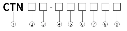
| Part Number: | CTN | 4 | S | - | 4 | 3A | 1 | R | ||
|---|---|---|---|---|---|---|---|---|---|---|
| Explanation: |
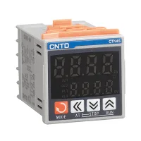
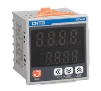
Series CTN - Standard digital dual display PID temperature controller |
Display Digits 4 - Four-digit, 9999 format, with separate PV and SV rows |
Panel Size S - 48×48mm |
Power Supply 2 - 24–48VAC/DC; AC frequency 50/60Hz |
Control Output 1 - Relay output |
Alarm Output 1 - One relay alarm |
Temperature Input Blank - Universal input without a code suffix: thermocouples K, E, J, L, T, R and S, or RTDs Pt100 and Cu50 |
Retransmission Output Blank - No separate retransmission output; omit this code |
Communication Blank - No communication function; omit this code |
CTN controllers combine two four-digit PV/SV displays, a 32-bit MCU and a 100ms sampling interval for temperature control. The range supports dual PID heating/cooling adjustment, automatic tuning, ON/OFF control and manual output. Five front formats cover 48mm square, 72mm square, 96mm square, vertical and horizontal panels.
The output choice determines how the controller connects to the process. Relay and SSR drive versions are available alongside analog current or voltage, SCR and combined relay/SSR options. RS485 communication and measurement retransmission are separate ordered functions. Select the complete hardware code rather than assuming an existing basic unit can provide every expansion through a menu setting.
| Field | Codes and meaning | Application of the option |
|---|---|---|
| Series | CTN: standard digital dual display PID controller; CTZ: high precision version in the wider guide | The complete models and ±0.5%FS specification on this page describe CTN. No separate CTZ accuracy is specified here. |
| Display | 4: four-digit, 9999 format, with separate PV and SV rows | The display format does not define a temperature input range. |
| Panel size | S: 48×48mm; V: 48×96mm; H: 96×48mm; M: 72×72mm; L: 96×96mm | H is the horizontal version and V the vertical version. |
| Supply | 2: 24–48VAC/DC; 4: 100–240VAC; M: 220VAC transformer version; BD: 24VAC transformer version | AC supplies use 50/60Hz. M and BD are additional transformer options in the current official guide; the common full models below use supply code 4. Letter combinations A–Z denote other custom supplies, whose exact code must accompany the specified version. |
| Control output | 1: relay; 2: SSR drive; 3A: analog current, 0–20mA or 4–20mA; 3B: analog voltage, 0–5V or 1–5V; 4: SCR zero-crossing output; 5: built-in 5A SCR; 6: relay plus SSR drive | The complete common 43A1 models are listed with 4–20mA control output. Other letter-coded outputs are custom versions. SSR drive and analog control output are different interfaces. |
| Alarm output | 1: one relay alarm; 2: two relay alarms; 3: one solid-state alarm; 4: two solid-state alarms; letter combinations: custom alarm version | Common full models use one or two relay alarms. |
| Temperature input | No code: thermocouples K, E, J, L, T, R or S; RTDs Pt100 or Cu50; letter combinations: custom input | The listed complete models use the universal input without a suffix. Configure the actual sensor type for the installation. |
| Retransmission | No code: absent; T: retransmission output | This is separate from the primary control output. A specific retransmission signal range is not given in this selection table. |
| Communication | No code: absent; R: RS485 communication | The common model table lists R versions and T versions separately. |
All 55 models below use 100–240VAC and universal thermocouple/RTD input. Each row preserves the control output, number of relay alarms, communication and retransmission relationship for the five panel formats.
| Configuration | 48×48mm | 48×96mm | 96×48mm | 72×72mm | 96×96mm |
|---|---|---|---|---|---|
| Relay control; one relay alarm | CTN4S-411 | CTN4V-411 | CTN4H-411 | CTN4M-411 | CTN4L-411 |
| Relay control; two relay alarms | CTN4S-412 | CTN4V-412 | CTN4H-412 | CTN4M-412 | CTN4L-412 |
| SSR drive; one relay alarm | CTN4S-421 | CTN4V-421 | CTN4H-421 | CTN4M-421 | CTN4L-421 |
| SSR drive; two relay alarms | CTN4S-422 | CTN4V-422 | CTN4H-422 | CTN4M-422 | CTN4L-422 |
| Relay plus SSR drive; one relay alarm | CTN4S-461 | CTN4V-461 | CTN4H-461 | CTN4M-461 | CTN4L-461 |
| 4–20mA control; one relay alarm | CTN4S-43A1 | CTN4V-43A1 | CTN4H-43A1 | CTN4M-43A1 | CTN4L-43A1 |
| Relay control; one relay alarm; RS485 | CTN4S-411R | CTN4V-411R | CTN4H-411R | CTN4M-411R | CTN4L-411R |
| SSR drive; one relay alarm; RS485 | CTN4S-421R | CTN4V-421R | CTN4H-421R | CTN4M-421R | CTN4L-421R |
| 4–20mA control; one relay alarm; RS485 | CTN4S-43A1R | CTN4V-43A1R | CTN4H-43A1R | CTN4M-43A1R | CTN4L-43A1R |
| Relay control; one relay alarm; retransmission | CTN4S-411T | CTN4V-411T | CTN4H-411T | CTN4M-411T | CTN4L-411T |
| SSR drive; one relay alarm; retransmission | CTN4S-421T | CTN4V-421T | CTN4H-421T | CTN4M-421T | CTN4L-421T |
Models without R have no communication function listed. Models without T have no separate retransmission function listed. The 4–20mA control signal in a 43A1 model is the primary control output and does not itself add a second retransmission channel.
| Characteristic | Specified value |
|---|---|
| Supply options | 100–240VAC or optional 24–48VAC/DC; AC frequency 50/60Hz |
| Power consumption | No more than 5VA |
| Sampling interval / measurement accuracy | 100ms / ±0.5%FS |
| Display resolution | 1°C or 0.1°C, adjustable |
| Operating environment | −10°C to +60°C; 35–85%RH, without condensation |
| Storage environment | −25°C to +65°C; avoid freezing and condensation |
| Memory / connection | Nonvolatile memory / terminal wiring |
| Installation conditions | Installation category II; pollution degree 2 |
| Relay control output | 3A at 220VAC or 30VDC |
| SSR logic drive | ON: 12VDC or 24VDC, depending on the output version; OFF: below 0.5VDC; maximum current 30mA |
SSR drive controls an external solid-state relay and is not a heater power output. The separate catalog contact certification entries list AC-15 at 380VAC and 250VAC, 3A, and DC-12 at 24–48VDC, 3A. These entries do not widen the controller supply range or replace the device relay output specification. The catalog cites CE and EN61010-1, with documents available from CNTD for the applicable version.
Dimensions are in millimeters. Cutout tolerances have zero negative deviation. The horizontal and vertical spacing figures are minimum centers between adjacent cutouts.
| Size code | Panel | Nominal shell size | Cutout | Minimum horizontal × vertical centers |
|---|---|---|---|---|
| CTN4S | 48×48 | 48×48×71 | 45(+0.6/0)×45(+0.6/0) | 65×65 |
| CTN4V | 48×96 | 48×96×71 | 46(+0.6/0)×92(+0.8/0) | 65×115 |
| CTN4H | 96×48 | 96×48×71 | 92(+0.8/0)×46(+0.6/0) | 115×65 |
| CTN4M | 72×72 | 72×72×71 | 68(+0.7/0)×68(+0.7/0) | 90×90 |
| CTN4L | 96×96 | 96×96×71 | 92(+0.8/0)×92(+0.8/0) | 115×115 |
| Size code | Front / rear side-view callouts | Additional side-view dimension |
|---|---|---|
| CTN4S | 6.5 / 67.9 | 55.3 |
| CTN4V | 6 / 65 | 91.5 |
| CTN4H | 6 / 65 | 91.5 along the long side in the shown view |
| CTN4M | 6 / 65 | 67 |
| CTN4L | 6 / 65 | 91.5 |
For CTN4S, reserve depth using the individual 6.5mm and 67.9mm side-view callouts rather than relying only on the nominal 71mm shell entry. Check mounting clip clearance and leave room for the terminals and wiring behind every size.
| Display or key | Purpose |
|---|---|
| PV row | Measured temperature and status prompts |
| SV row | Setpoint and parameter values |
| OUT | Heating/output indicator, lit during output operation |
| AL1 / AL2 | Alarm channel 1 / channel 2 indicators; upper-limit / lower-limit alarms are the stated defaults |
| Up | Increase values, enter manual mode and switch menu/parameter items |
| Down | Decrease values, access tuning and switch menu/parameter items |
| Left shift | Select units, tens, hundreds or thousands; a long press on the home screen enters tuning mode |
| Mode | Enter main/submenus, modify parameters and confirm settings |
The illustrated heater loop feeds the temperature sensor back to the controller and drives the heater through an external SSR. The control diagrams also show ON/OFF operation and manual output, with 50% and 80% examples over a 50-cycle window. Choose the actual output interface and switching device for the load; the different hardware output options are not interchangeable power terminals.
Applications illustrated in the catalog include printing, ceramic machinery, rubber and plastics machinery, packaging, injection molding and food machinery. The manufacturer requires a specially designed version and written confirmation for high reliability energy systems, applications involving personal safety or major property risk, harsh or outdoor environments, fire or explosion risks, and military or aerospace applications.
