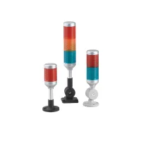
CTM50 multifunction signal towers offer one to five LED color layers with selectable flashing or steady illumination. Add intermittent or continuous sound, choose a disc, side-nut or folding mount, and specify the rod and cable configuration.
The D supply configuration is adjustable for the listed settings of 12VAC/DC, 24VAC/DC or 220VAC. Match the selected supply configuration before energizing. SMD LEDs illuminate prism-pattern PC lenses above an ABS base. The high-brightness LED components have a typical life reference above 50,000 hours, separate from complete-assembly service life.
| Field | Code | Selection |
|---|---|---|
| Series | CTM | Multifunction multilayer warning light |
| Size | 50 | Nominal Ø50mm light body |
| Layer colors | R | Red; one layer |
| RG | Red / green; two layers | |
| RYG | Red / yellow / green; three layers | |
| RYGB | Red / yellow / green / blue; four layers | |
| RYGBW | Red / yellow / green / blue / white; five layers | |
| Custom | Other color combinations may be specified | |
| Sound | Omitted | No sound |
| A | Intermittent beep | |
| B | Continuous sound | |
| Light operation | S | Selectable flashing / steady; factory setting is steady |
| Supply configuration | D | Adjustable for12VAC/DC, 24VAC/DC or220VAC |
| Function | Omitted | Regular version; IP43 single-light protection |
| F | IP65 version | |
| K | Anti-interference version | |
| Mounting base | A | Disc mount; default base |
| B | Side-nut mount | |
| C | 90° square folding mount | |
| D | 90° circular folding mount | |
| Rod length | 10 | 100mm |
| 15 | 150mm | |
| 26 | 260mm | |
| Other number | Custom length for the selected mount | |
| Cable length | L06 | 0.6m |
| L1–L5 | L1 indicates1m; cable length is not limited to L5 | |
| Connection | Omitted | Free cable ends |
| M… | M-type connector; specify complete connector details | |
| D… | DT-type connector; specify complete connector details | |
| A… | AMP-type connector; specify complete connector details | |
| S… | SM-type connector; specify complete connector details | |
| Cable material | Omitted | PVC |
| U | PUR sheathed cable | |
| VP | Shielded PVC sheathed cable | |
| UP | Shielded PUR sheathed cable |
CTM50-RYG/ASD-A10L06 is a three-layer red/yellow/green configuration with intermittent sound, selectable light, D adjustable supply, disc base, 100mm rod and 0.6m cable.

All 60 models below use S selectable flashing/steady operation, initially steady, the D adjustable supply configuration and a 0.6m cable. A10 and C10 include a 100mm rod; B26 includes a 260mm rod. Circular-folding D examples have no separate rod-length code.
| Colors / mount | No sound | Intermittent beep | Continuous sound |
|---|---|---|---|
| R / A10 disc | CTM50-R/SD-A10L06 | CTM50-R/ASD-A10L06 | CTM50-R/BSD-A10L06 |
| R / B26 side nut | CTM50-R/SD-B26L06 | CTM50-R/ASD-B26L06 | CTM50-R/BSD-B26L06 |
| R / C10 square folding | CTM50-R/SD-C10L06 | CTM50-R/ASD-C10L06 | CTM50-R/BSD-C10L06 |
| R / D circular folding | CTM50-R/SD-DL06 | CTM50-R/ASD-DL06 | CTM50-R/BSD-DL06 |
| RG / A10 disc | CTM50-RG/SD-A10L06 | CTM50-RG/ASD-A10L06 | CTM50-RG/BSD-A10L06 |
| RG / B26 side nut | CTM50-RG/SD-B26L06 | CTM50-RG/ASD-B26L06 | CTM50-RG/BSD-B26L06 |
| RG / C10 square folding | CTM50-RG/SD-C10L06 | CTM50-RG/ASD-C10L06 | CTM50-RG/BSD-C10L06 |
| RG / D circular folding | CTM50-RG/SD-DL06 | CTM50-RG/ASD-DL06 | CTM50-RG/BSD-DL06 |
| RYG / A10 disc | CTM50-RYG/SD-A10L06 | CTM50-RYG/ASD-A10L06 | CTM50-RYG/BSD-A10L06 |
| RYG / B26 side nut | CTM50-RYG/SD-B26L06 | CTM50-RYG/ASD-B26L06 | CTM50-RYG/BSD-B26L06 |
| RYG / C10 square folding | CTM50-RYG/SD-C10L06 | CTM50-RYG/ASD-C10L06 | CTM50-RYG/BSD-C10L06 |
| RYG / D circular folding | CTM50-RYG/SD-DL06 | CTM50-RYG/ASD-DL06 | CTM50-RYG/BSD-DL06 |
| RYGB / A10 disc | CTM50-RYGB/SD-A10L06 | CTM50-RYGB/ASD-A10L06 | CTM50-RYGB/BSD-A10L06 |
| RYGB / B26 side nut | CTM50-RYGB/SD-B26L06 | CTM50-RYGB/ASD-B26L06 | CTM50-RYGB/BSD-B26L06 |
| RYGB / C10 square folding | CTM50-RYGB/SD-C10L06 | CTM50-RYGB/ASD-C10L06 | CTM50-RYGB/BSD-C10L06 |
| RYGB / D circular folding | CTM50-RYGB/SD-DL06 | CTM50-RYGB/ASD-DL06 | CTM50-RYGB/BSD-DL06 |
| RYGBW / A10 disc | CTM50-RYGBW/SD-A10L06 | CTM50-RYGBW/ASD-A10L06 | CTM50-RYGBW/BSD-A10L06 |
| RYGBW / B26 side nut | CTM50-RYGBW/SD-B26L06 | CTM50-RYGBW/ASD-B26L06 | CTM50-RYGBW/BSD-B26L06 |
| RYGBW / C10 square folding | CTM50-RYGBW/SD-C10L06 | CTM50-RYGBW/ASD-C10L06 | CTM50-RYGBW/BSD-C10L06 |
| RYGBW / D circular folding | CTM50-RYGBW/SD-DL06 | CTM50-RYGBW/ASD-DL06 | CTM50-RYGBW/BSD-DL06 |
| Color | 12VDC | 24VDC | 220VAC | |||
|---|---|---|---|---|---|---|
| Maximum current | Rounded DC power | Maximum current | Rounded DC power | Maximum current | Power | |
| Red | 32mA | 0.38W | 33mA | 0.79W | 53mA | 0.55W |
| Yellow | 27mA | 0.32W | 0.59W | |||
| Green | 19mA | 0.23W | 0.6W | |||
| Blue | 27mA | 0.32W | 0.7W | |||
| White | 34mA | 0.4W | 41mA | 0.98W | 51mA | |
DC power is a rounded calculation from nominal voltage and maximum color-channel current. AC power and current are separate specifications. These values do not specify the total power of every possible stack and sound configuration.
| LED bead color | Bead voltage |
|---|---|
| Red | 1.8–2.2V |
| Yellow | |
| Green | 2.8–3.4V |
| Blue | |
| White |
LED bead voltage is a component reference, not the supply voltage for the assembled tower.
| Parameter | Specification |
|---|---|
| Sound level | A intermittent-sound version: maximum85dB; test distance unspecified |
| Flashing rate | 55–65 flashes/min; nominal60 flashes/min |
| Lens / base | PC / ABS |
| Cord specification | UL1007 |
| Ambient temperature | −30°C to +50°C |
| Relative humidity | ≤85% |
| Protection | Regular single light: IP43; F option: IP65 |
| Altitude | ≤2000m |
| Compliance reference | Standard | Document reference |
|---|---|---|
| CCC | GB/T14048.5 | Document number not specified |
| CE | EN61058 |
| Layers / colors | Light-body height | Nominal diameter |
|---|---|---|
| 1 / R | 105mm | 50mm |
| 2 / RG | 159mm | |
| 3 / RYG | 213mm | |
| 4 / RYGB | 267mm | |
| 5 / RYGBW | 321mm |
Light-body heights exclude the rod and base. The drawings show side-nut, disc, square-folding and circular-folding configurations for each layer count. Dimensions are in mm.


| Mount / bracket | Dimensional references in mm |
|---|---|
| A / CTL50-MA disc | BaseØ70; mounting circleØ55; four Ø5 holes withØ11 counterbores; rodØ18; full bracket section90; installed base projection44.5 |
| B / CTL50-MB side nut | Bracket32×78, inner width25; two Ø12 holes,22 center spacing and10 lower-edge reference; projection45; rod openingØ18; illustrated installed extension82 |
| C / CTL50-MC square folding | Base72×72; four Ø6 holes on53×53 centers; height114; rodØ18 |
| D / CTL50-MD circular folding | BaseØ70; four Ø5 holes onØ55 circle; full bracket110; installed projection80; threaded section35; rodØ18 |

| Wire designation | Function in the five-layer reference |
|---|---|
| R / red | Layer1 |
| Y / yellow | Layer2 |
| G / green | Layer3 |
| B / blue | Layer4 |
| W / white | Layer5 |
| P / purple | Buzzer |
| GY / gray | Common line |
External contacts control the individual light and buzzer circuits. Connect the selected supply and polarity arrangement. The illustrated mode jumper is open for flashing and linked for steady illumination.

Rotate a lens module counterclockwise until its marks align, then pull upward to remove it. To assemble, align the marks, press downward and rotate clockwise until the triangular mark reaches the index.

Keep the cable outlet from facing upward. Regular IP43 versions require upright vertical installation because their water protection is below IPX4. Use the selected bracket's fixing pattern, tighten the mounting hardware and protect the cable from impact and abrasion.

Disconnect power before installation, wiring, work on the assembly or maintenance. Check the configured supply voltage, secure the installation and prevent conductive liquid, dust and other debris from entering. Qualified personnel should service complex faults and high-voltage components.
These products are intended for industrial signaling. High-reliability infrastructure, personal-safety systems, harsh environments, fire or explosion hazards, military uses and aerospace projects require a specifically designed and expressly confirmed configuration.
