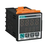


| Part Number: | CTE | 4 | S | - | 4 | 2 | 1 | |
|---|---|---|---|---|---|---|---|---|
| Explanation: |
Series CTE - Economical digital dual display PID temperature controller |
Display Digits 4 - Four-digit display format, 9999; separate PV and SV rows |
Panel Size S - 48×48mm |
Power Supply 4 - 100–240VAC, 50/60Hz |
Control Output 1 - Relay output |
Alarm Output 1 - One relay alarm |
Universal Temperature Input Blank - Universal input adds no code suffix: thermocouples K, E, J, L, T, R and S, or RTDs Pt100 and Cu50. Select the appropriate sensor input before operation. |
CTE controllers provide two rows of four-digit indication for the measured process value, PV, and the setpoint or parameter value, SV. The range combines a 32-bit MCU, high speed sampling, the manufacturer's AI adjustment algorithm and AT automatic tuning. Four panel sizes suit compact square, vertical and larger square installations. Control choices include PID heating, PID cooling, ON/OFF heating and ON/OFF cooling.
Select the output hardware as well as the panel size. Relay, SSR drive, and combined relay plus SSR drive versions are listed, with separate alarm output choices. The SSR drive is a low voltage control signal for an external solid-state relay; it is not a power output for connecting a heater directly. Standard common models have universal temperature input and no communication option listed.

| Ordering field | Available choices |
|---|---|
| Display | 4: four-digit, 9999 display format; separate PV and SV rows |
| Panel size | S: 48×48mm; V: 48×96mm; M: 72×72mm; L: 96×96mm |
| Supply | 4: 100–240VAC, 50/60Hz |
| Control output | 1: relay; 2: SSR drive; 6: relay plus SSR drive |
| Alarm output | 1: one relay alarm; 2: two relay alarms; 3: one solid-state alarm; 4: two solid-state alarms |
| Input | No additional code: thermocouples K, E, J, L, T, R or S; RTDs Pt100 or Cu50 |
Alarm codes 3 and 4 are broader ordering-guide options. The complete common selections below use one or two relay alarms; choose the exact hardware version rather than assuming alarm type can be changed through a setting.
| Control output | Relay alarms | 48×48mm | 48×96mm | 72×72mm | 96×96mm |
|---|---|---|---|---|---|
| Relay | One | CTE4S-411 | CTE4V-411 | CTE4M-411 | CTE4L-411 |
| Relay | Two | CTE4S-412 | CTE4V-412 | CTE4M-412 | CTE4L-412 |
| SSR drive | One | CTE4S-421 | CTE4V-421 | CTE4M-421 | CTE4L-421 |
| SSR drive | Two | CTE4S-422 | CTE4V-422 | CTE4M-422 | CTE4L-422 |
| Relay plus SSR drive | One | CTE4S-461 | CTE4V-461 | CTE4M-461 | CTE4L-461 |
All twenty common models use 100–240VAC, accept the listed thermocouple and RTD inputs, and show no communication function in the common-model tables. Select and configure the sensor input appropriate to the installation before operation.
| Characteristic | Specified value or condition |
|---|---|
| Supply / power consumption | 100–240VAC, 50/60Hz; no more than 5VA |
| Measurement accuracy | ±0.5%FS |
| Display resolution | 1°C or 0.1°C, adjustable |
| Operating environment | −10°C to +60°C; 35–85%RH, without condensation |
| Storage environment | −25°C to +65°C; avoid freezing and condensation |
| Parameter memory | Nonvolatile memory |
| Connection | Terminal connection |
| Installation conditions | Installation category II; pollution degree 2 |
| Relay control output | 3A at 220VAC or 30VDC |
| SSR logic drive output | ON: 12VDC; OFF: below 0.5VDC; maximum current 30mA |
The catalog separately lists contact certification duty entries of AC-15 at 380VAC and 250VAC, 3A, and DC-12 at 24–48VDC, 3A. These are separate contact duty entries, rather than a wider controller supply range or a replacement for the relay output specification above. The catalog references CE and EN61010-1; obtain the applicable document from CNTD for a project requiring that evidence.
Dimensions are in millimeters. Cutout tolerances are positive only: the lower deviation is zero. Spacing values are the minimum centers between adjacent panel cutouts, rather than the clear gap between instruments.
| Model size | Panel | Nominal shell size | Cutout | Minimum horizontal × vertical centers |
|---|---|---|---|---|
| CTE4S | 48×48 | 48×48×71 | 45(+0.6/0)×45(+0.6/0) | 65×65 |
| CTE4V | 48×96 | 48×96×71 | 46(+0.6/0)×92(+0.8/0) | 65×115 |
| CTE4M | 72×72 | 72×72×71 | 68(+0.7/0)×68(+0.7/0) | 90×90 |
| CTE4L | 96×96 | 96×96×71 | 92(+0.8/0)×92(+0.8/0) | 115×115 |
| Model size | Front and rear side-view callouts | Side-view vertical dimension |
|---|---|---|
| CTE4S | 6.5 front; 67.9 rear | 55.3 |
| CTE4V | 6 front; 65 rear | 91.5 |
| CTE4M | 6 front; 65 rear | 67 |
| CTE4L | 6 front; 65 rear | 91.5 |
For CTE4S, check the 6.5mm and 67.9mm side-view callouts when reserving depth; the general table lists a nominal 71mm shell dimension. Use the individual drawing and allow space for the mounting clips, terminals and wiring.
| Display or control | Function |
|---|---|
| PV display | Measured temperature and instrument status prompts |
| SV display | Setpoint and parameter values |
| OUT | Heating/output indication; lit while the output is operating |
| AL1 / AL2 | High-limit / low-limit alarm indication; lit during the corresponding alarm |
| Up key | Increase a value, enter manual mode, and switch menu/parameter items as configured |
| Down key | Decrease a value and switch menu/parameter items |
| Left shift / AT key | Move the selected digit and enter the tuning state |
| Mode key | Enter main and submenus, modify parameters and confirm settings |
With a suitable temperature sensor and external power switching device, CTE can regulate heaters in printing, ceramic, rubber and plastics, packaging, injection molding and food machinery. The illustrated control loop returns the sensor signal to the controller and drives an external SSR between the controller and heater. ON/OFF control and manual output are also shown; the manual output examples illustrate 50% and 80% conduction over a 50-cycle window.
The manufacturer requires specially designed equipment and written confirmation for high reliability energy systems, applications involving personal safety or major property risk, harsh or outdoor conditions, fire or explosion risks, and military or aerospace use. Select the controller, sensor, switching device and independent protective functions for the actual process.
