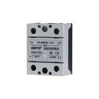


| Part Number: | CSR | E | - | 40 | DA | R |
|---|---|---|---|---|---|---|
| Explanation: |
Series CSR - Single-phase solid-state relay family |
Housing Omitted - Standard type with light-green housing |
Load current 10 - 10A |
Control and load DA - DC control with AC load |
Turn-on mode Omitted - Standard zero-cross turn-on for AC switching |
CSR solid-state relays use power semiconductors for contactless industrial switching. Single-phase CSR and three-phase CTR configurations are available in standard light-green housings or gray E economy housings. DA selects DC control of an AC load, AA selects AC control of an AC load, DD selects DC control of a DC load, and VA selects external-potentiometer AC regulation.
Zero-cross turn-on waits for the load voltage to enter the zero region, with up to a half-cycle turn-on delay, reducing load impact and radio-frequency interference. Random turn-on responds to the control signal immediately. AC thyristor outputs turn off when current falls below the holding current. Enhanced antiparallel-thyristor construction has a commutating dv/dt reference of 500V/µs, compared with 300V/µs for the conventional triac reference. Applications include temperature and lighting regulation, automation, CNC, packaging, textile, glass and plastics machinery.
Current options are separate rated selections. VA models use a 500kΩ, 0.25W external potentiometer. Their control specification is a resistance and power rating, rather than a control-voltage range.
| Model pattern | Current options | Load voltage | Control input | Control current | On-state drop | Off-state leakage |
|---|---|---|---|---|---|---|
| CSRE-DA | 10A, 25A, 40A, 60A, 80A, 100A | 24–480VAC | 4–32VDC | 3–25mA DC | ≤1.5V | ≤10mA at 10–40A; ≤20mA at 60–100A |
| CSRE-AA | 90–250VAC | ≤12mA AC | ||||
| CSRE-VA | 10A, 25A, 40A | 10–250VAC | 500kΩ, 0.25W potentiometer | Not applicable | ≤5mA | |
| CSRE-DD | 12–250VDC | 3–32VDC | 3–25mA DC | ≤2.3V | ||
| CTRE-DA | 10A, 25A, 40A, 60A, 80A, 100A, 120A | 40–480VAC | 4–32VDC | 3–25mA DC | ≤1.5V | ≤15mA |
| CSR-DA | 10A, 25A, 40A, 60A, 80A, 100A | 24–480VAC | 4–32VDC | 3–25mA DC | ≤10mA at 10–40A; ≤20mA at 60–100A | |
| CSR-AA | 80–250VAC | ≤12mA AC | ||||
| CSR-VA | 10A, 25A, 40A | 10–250VAC | 500kΩ, 0.25W potentiometer | Not applicable | ≤5mA | |
| CSR-DD | 12–250VDC | 3–32VDC | 3–25mA DC | ≤2.3V | ||
| CTR-DA | 10A, 25A, 40A, 60A, 80A, 100A, 120A | 40–480VAC | 4–32VDC | 3–25mA DC | ≤1.5V | ≤15mA |
For these ten patterns, turn-off time is ≤10ms, isolation voltage is 2500VAC, insulation resistance is 1000MΩ at 500VDC, and operating temperature is -30–80°C. The additional CTRE-AA and CTR-AA outlines below have 10A through 120A model references, 40–480VAC load markings and an AA control selection of 80–250VAC. Their detailed control-current, voltage-drop and leakage values are unspecified.
| Model family | Complete references |
|---|---|
| CSRE-DA | CSRE-10DA, CSRE-25DA, CSRE-40DA, CSRE-60DA, CSRE-80DA, CSRE-100DA |
| CSRE-AA | CSRE-10AA, CSRE-25AA, CSRE-40AA, CSRE-60AA, CSRE-80AA, CSRE-100AA |
| CSRE-VA | CSRE-10VA, CSRE-25VA, CSRE-40VA |
| CSRE-DD | CSRE-10DD, CSRE-25DD, CSRE-40DD |
| CTRE-DA | CTRE-10DA, CTRE-25DA, CTRE-40DA, CTRE-60DA, CTRE-80DA, CTRE-100DA, CTRE-120DA |
| CTRE-AA | CTRE-10AA, CTRE-25AA, CTRE-40AA, CTRE-60AA, CTRE-80AA, CTRE-100AA, CTRE-120AA |
| CSR-DA | CSR-10DA, CSR-25DA, CSR-40DA, CSR-60DA, CSR-80DA, CSR-100DA |
| CSR-AA | CSR-10AA, CSR-25AA, CSR-40AA, CSR-60AA, CSR-80AA, CSR-100AA |
| CSR-VA | CSR-10VA, CSR-25VA, CSR-40VA |
| CSR-DD | CSR-10DD, CSR-25DD, CSR-40DD |
| CTR-DA | CTR-10DA, CTR-25DA, CTR-40DA, CTR-60DA, CTR-80DA, CTR-100DA, CTR-120DA |
| CTR-AA | CTR-10AA, CTR-25AA, CTR-40AA, CTR-60AA, CTR-80AA, CTR-100AA, CTR-120AA |
Standard green housings are also illustrated with CSRM or CSRT body markings. Select by the complete model and its control and load ratings.

Broader application references below are separate from the complete model list: the general range is 0.5–400A and 12–680V, with DC/AC, AC/AC and DC/DC input/output choices and an unspecified IEC standard reference. An industrial-class reference extends to 100–800A; these ranges do not assign an additional complete model or expand a listed model's rating.
| Application class | Control voltage | Control current | Start current | Control off voltage | Operating current | Operating voltage | Protection |
|---|---|---|---|---|---|---|---|
| CSR DC/AC | 4–32VDC | 3–25mA | ≥5mA | ≤1.5VDC | 10–100A | 24–480VAC | RC/MOV; fast fuse |
| CSR AC/AC | 80–250VAC | <30mA | ≤10VAC | ||||
| Industrial class | 4–32VDC | <20mA | ≤1.5VDC | 100–800A | |||
| CSR DC/DC | 3–32VDC | 3–25mA | ≤1.5VDC | 10–40A | 12–250VDC | Diode | |
| CTR | 4–32VDC | <30mA | ≥9mA | ≤2.5VDC | 10–120A | 40–480VAC | RC/MOV; fast fuse |
| Solid-state voltage regulator | 500kΩ, 0.25W external potentiometer | 10–40A | 10–250VAC | ||||
This application guide specifies isolation of ≥2500VAC and general safe-load references of 60% for resistive loads and 40% for inductive loads. RC denotes a built-in resistor-capacitor absorption circuit; MOV denotes an external parallel metal-oxide varistor. Start-current and control-off thresholds are separate from the model-specific input-current range.
| Load type | Room-temperature reference ratio |
|---|---|
| Pure resistance | 100% |
| Heating wire | 50–70% |
| Incandescent lamp | 35–50% |
| Transformer or electromagnet | 25–40% |
| Single-phase AC motor | 12–24% |
| Three-phase AC motor | 18–33% |
Continuous current must remain at or below 70% of nominal current, with heatsink temperature no higher than 75°C. The room-temperature ratios do not override continuous-operation, safe-load or temperature limits. Prevent a load short circuit, use appropriate fast-fuse protection and add a varistor for inductive loads.


Dimensions are in mm. Single-phase models have a 44.5×59×29 body, 47.5 mounting-center spacing, Ø4.5 fixing holes, two M5 output terminals and two M4 input terminals. Three-phase models have a 104.5×73.5×33 body, 91.6 and 47.6 mounting dimensions, six M5 power terminals and two M3 control terminals.


| Standard configuration | Current group | Weight |
|---|---|---|
| CSR-DA and CSR-AA | 10–40A | 90g |
| 60–100A | 140g | |
| CSR-VA and CSR-DD | 10–40A | 90g |
| CTR-DA | 10–40A | 350g |
| 60–120A | 450g |

| Heatsink | Assigned current group | Dimensions and fixing references in mm |
|---|---|---|
| CSR-A01 | CSR 10–40A | 75×50 plan, 44 height; 47.5 fixing pitch; 4.5 slot width |
| CSR-A02 | CSR 60–100A | 125×68 plan, 50 height; 47.5 fixing pitch |
| CTR-A03 | CTR 10–120A | 100 base width, 80 upper width and 80 height; transverse fixing pitch 47.5; inner longitudinal pitch 90; outer longitudinal pitch 130 |


| Marking reference | Standard | Document reference |
|---|---|---|
| CCC | GB/T14048.5 | Available on request; no document number specified |
| CE | EN60947-5-1 |
A separate safety-rating reference lists AC-12/DC-12, 24–660VAC and resistive current selections of 10A, 25A, 40A, 60A, 80A, 100A and 120A. This reference does not expand the operating voltage of an individual model.
These products are intended for industrial control. Exceptionally high-reliability or safety applications, including nuclear, gas and power systems and situations involving personal safety or property, require a specially designed product and written application approval. The same requirement applies to harsh outdoor, chemically contaminated, electromagnetic, vibration or shock environments; fire or explosion hazards involving flammable gases, strong acids or alkalis; military uses and aerospace projects.
