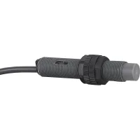


These cylindrical capacitive proximity sensors use plastic housings in M12, M18 and M30 sizes. Select the sensing distance and working range together, then choose the supply and output circuit. The DC range includes NPN and PNP versions with normally open, normally closed or combined outputs, subject to the model combinations below. AC versions use a two-wire output. A red LED indicates operation.
| Models | Housing | Sensing distance | Setting distance | Supply | Output options |
|---|---|---|---|---|---|
| CRY12-02DNA CRY12-02DNB CRY12-02DPA CRY12-02DPB | M12 | 2mm | 0-1.4mm | 10-30VDC | NPN or PNP; NO or NC; three-wire |
| CRY12-04DNA CRY12-04DNB CRY12-04DPA CRY12-04DPB | 4mm | 0-2.8mm | |||
| CRY18-05DNA CRY18-05DNB CRY18-05DNC CRY18-05DPA CRY18-05DPB CRY18-05DPC | M18 | 5mm | 0-3.5mm | NPN or PNP; NO, NC or NO+NC; three-wire for NO/NC, four-wire for combined outputs | |
| CRY18-08DNA CRY18-08DNB CRY18-08DNC CRY18-08DPA CRY18-08DPB CRY18-08DPC | 8mm | 0-5.6mm | |||
| CRY30-10DNA CRY30-10DNB CRY30-10DNC CRY30-10DPA CRY30-10DPB CRY30-10DPC | M30 | 10mm | 0-7mm | ||
| CRY30-15DNA CRY30-15DNB CRY30-15DNC CRY30-15DPA CRY30-15DPB CRY30-15DPC | 15mm | 0-10.5mm |
In the suffix, D identifies the DC supply, N identifies NPN and P identifies PNP. The final A means NO, B means NC and C means NO+NC. Combined-output M12 models are not included in this selection.
| Models | Housing | Sensing distance | Setting distance | Supply | Output |
|---|---|---|---|---|---|
| CRY12-08AKA CRY12-08AKB | M12 | 5mm | 0-3.5mm | 90-250VAC | AC two-wire; final A = NO, final B = NC |
| CRY18-08AKA CRY18-08AKB | M18 | 8mm | 0-5.6mm | ||
| CRY30-10AKA CRY30-10AKB | M30 | 10mm | 0-7mm | ||
| CRY30-15AKA CRY30-15AKB | 15mm | 0-10.5mm |
The AC M12 models CRY12-08AKA and CRY12-08AKB use the 5mm sensing distance and 0-3.5mm setting range shown above. Select them by these model-specific values.
| Parameter | DC models | AC models |
|---|---|---|
| Hysteresis | Maximum 10% of sensing distance | |
| Response frequency | 50Hz; measurement conditions are not specified | |
| Leakage current | Maximum 10mA | |
| Residual voltage | Maximum 1V | Maximum 10V |
| Control output | Maximum 200mA | |
| Temperature effect | Within ±10% of sensing distance over -25°C to +60°C, referenced to +20°C | |
| Insulation resistance | At least 50MΩ at 500VDC | |
| Dielectric strength | 1500VAC, 50/60Hz, for 1 minute | |
| Vibration resistance | 1mm amplitude, 10-55Hz with a 1 minute frequency cycle; 2 hours in each X, Y and Z direction | |
| Shock resistance | 500m/s², approximately 50G; three shocks in each X, Y and Z direction | |
| Operation indicator | Red LED | |
| Operating temperature | -25°C to +60°C, without icing | |
| Storage temperature | -30°C to +80°C, without icing | |
| Ambient humidity | 35-95%RH, without condensation | |
| Protection circuits | Surge, reverse polarity and overcurrent protection | Surge protection |
| Housing and sensing surface | ABS case and nut; PBT sensing surface | |
| Washer | Plastic | Not separately specified |
| Cable materials and colors | Standard gray PVC cable; oil-resistant black PVC cable. Optional PUR and shielded constructions are selected separately. | |
| Enclosure protection | IP65 | |
| Model group | Standard cable | Construction references |
|---|---|---|
| M12 DC models | Ø3.8mm, three conductors, 2m | AWG22 designation; 25 strands of Ø0.1mm per conductor; insulation outside diameter Ø1.25mm |
| M18 and M30 DC models | Ø4.8mm, three or four conductors according to output configuration, 2m | AWG22 designation; 30 strands of Ø0.1mm per conductor; insulation outside diameter Ø1.25mm |
| AC two-wire models | Ø4.8mm, two conductors, 2m |

| Position | Option | Code | Meaning and applicability |
|---|---|---|---|
| 1 | Classification | CR | Capacitive proximity sensor |
| 2 | Housing shape | Y | Cylindrical plastic housing |
| YM | Cylindrical copper-tube housing configuration; obtain its matching dimensions before selection | ||
| 3 | Housing size | 12, 18, 30 | M12, M18 and M30 respectively |
| 4 | Product type | Omitted | Standard form |
| 5 | Thread length | Omitted | Normal thread |
| L | Long-thread option; obtain the corresponding dimensions | ||
| 6 | Distance selections | 02, 04, 05, 08, 10, 15 | Common DC distance selections are 2mm, 4mm, 5mm, 8mm, 10mm and 15mm. The exact model tables govern availability and the AC M12 exception. |
| 7 | Supply | D | 10-30VDC |
| A | 90-250VAC operating supply | ||
| 8 | Output circuit | N | NPN DC output |
| P | PNP DC output | ||
| K | AC two-wire output | ||
| 9 | Output state | A | Normally open |
| B | Normally closed | ||
| C | Combined NO+NC, for the listed M18 and M30 DC models | ||
| 10 | Connection form | Omitted | Cable with free lead end |
| M | Direct M12 straight four-pin, A-coded connector | ||
| M plus connector-selection code | M-type cable connector configuration | ||
| D plus connector-selection code | DT-type connector configuration | ||
| A plus connector-selection code | AMP-type connector configuration | ||
| S plus connector-selection code | SM-type connector configuration | ||
| 11 | Cable material | Omitted | PVC |
| U | PUR | ||
| VP | Shielded PVC | ||
| UP | Shielded PUR | ||
| 12 | Cable length | Omitted | Direct M-connector body connection |
| L1-L5 | 1m to 5m, with L1 meaning 1m; other lengths can be specified |
Specify the complete connector-selection code and verify the connector, cable and output combination for the chosen model.
| Reference designation | Standard | Documentation |
|---|---|---|
| CCC | GB/T 14048.10 | Check documentation for the exact model and configuration. |
| TUV | EN 60947-5-2 | |
| CE |
| Utilization category | Reference rating | Operating-supply requirement |
|---|---|---|
| AC-140 | 200mA at 24-250VAC | Use the model's 90-250VAC operating range |
| DC-13 | 200mA at 10-30VDC | 10-30VDC |
| Model | Length references | Body and nut references | Additional details |
|---|---|---|---|
| CRY12-04 | 62.71mm overall; 55mm body reference | 11.7mm body reference; 17.2mm nut span | 3.6mm feature dimensions; LED and VR adjustment positions shown in the drawing |
| CRY18-08 | 65.3mm overall; 55mm reference | 18.44mm body reference; 22.53mm nut span | 3.5mm and 4.5mm feature dimensions |
| CRY30-10 | 67mm overall; 60mm reference | 30.8mm body reference; 37.58mm nut span | 4.5mm and 5.5mm feature dimensions |
Use the attachment to identify each dimension's feature and view. Long-thread and alternative housing configurations require their corresponding drawings.
These sensors are intended for ordinary industrial control. Nuclear, gas or power systems requiring exceptional reliability, personal-safety functions, harsh outdoor or contaminated environments, fire or explosion hazards, military use and aerospace require a specifically designed and confirmed configuration.
