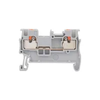
CPT push-in terminal blocks provide NS35 rail connections in feed-through, multi-level, disconnect and fuse configurations. Integrated test points allow testing without removing conductors or bridges. Bridge wells support cross-connections, with matching end plates, markers and end clamps selected for each model.
The tables below distinguish30 non-PE configurations, including the CPP-H2.5 individual plug component. Select by conductor range, rated current and voltage, outline dimensions and accessory reference. Different connection technologies can be combined in a terminal assembly with the corresponding bridging, marking and test accessories.
Rigid and flexible ranges are listed separately in mm². AWG ranges are independent selection references. The maximum-load column preserves its stated conductor condition; it is separate from the rated-current column and does not specify a continuous-duty condition.
| Model | AWG | Rigid / flexible conductor in mm² | Rated current | Rated voltage | Maximum-load reference |
|---|---|---|---|---|---|
| CPT-1.5 | 26–14 | 0.2–1.5 /0.2–1.5 | 17.5A | 500V | Not separately specified |
| CPT-1.5/2 | 16A | ||||
| CPT-1.5/1-2 | 17.5A | ||||
| CPT-1.5/2-2 | 17.5A | ||||
| CPT-1.5/2L | 16A | ||||
| CPT-1.5/2K | 9A | 400V | |||
| CPT-2.5 | 26–12 | 0.2–4 /0.2–4 | 24A | 800V | 28A with4mm² rigid conductor |
| CPT-2.5/2 | 22A | 500V | 26A with4mm² rigid conductor | ||
| CPT-2.5/1-2 | 24A | 800V | 28A with4mm² rigid conductor | ||
| CPT-2.5/2-2 | 24A | ||||
| CPT-2.5/2L | 26–14 | 22A | 500V | 26A with4mm² rigid conductor | |
| CPT-2.5/1-2K | 26–12 | 20A | 400V | 20A with2.5mm² rigid conductor | |
| CPT-2.5/K | |||||
| CPT-2.5/1P | 24A | 500V | 24A with4mm² rigid conductor | ||
| CPP-H2.5 | 26–12 | 0.2–4 /0.2–2.5 | 24A | 500V | 24A with4mm² rigid conductor |
| CPT-4 | 24–10 | 0.2–6 /0.2–6 | 32A | 800V | 36A with6mm² rigid conductor |
| CPT-4/2 | 28A | 500V | 32A with6mm² rigid conductor | ||
| CPT-4/1-2 | 32A | 800V | 36A with6mm² rigid conductor | ||
| CPT-4/2-2 | |||||
| CPT-4/2L | 30A | 500V | 32A with6mm² rigid conductor | ||
| CPT-6 | 20–8 | 0.5–10 /0.5–10 | 41A | 1000V | 52A with6mm² rigid conductor |
| CPT-6/1-2 | |||||
| CPT-6/2-2 | |||||
| CPT-10 | 20–6 | 0.5–16 /0.5–16 | 57A | 70A with16mm² rigid conductor | |
| CPT-10/1-2 | |||||
| CPT-16 | 20–4 | 0.5–25 /0.5–25 | 76A | 85A with25mm² rigid conductor | |
| CPT-4RD/C | 24–10 | 0.2–6 /0.2–6 | 6.3A | 500V | 6.3A with6mm² rigid conductor |
| CPT-4RD/C/LA250 | 250V | ||||
| CPT-4RD/C/LED24 | 24V | ||||
| CPT-4RD/C/LED60 | 60V |
CPP-H2.5 is an individual plug component with two concave interfaces and can be used individually. Its flexible-conductor limit is2.5mm². The CPT-4RD/C family comprises fuse terminal configurations; the voltage ratings above remain specific to each complete model.
Dimensions are in mm, in the listed order: thickness, width, body height and height on the NS35 rail. CPP-H2.5 has three listed outline dimensions; a separate rail-mounted height is unspecified. Color codes are GY gray, BE blue, RD red and BK black.
| Model | Thickness | Width | Body height | NS35 height | Colors |
|---|---|---|---|---|---|
| CPT-1.5 | 3.5 | 45 | 30.5 | 32 | GY / BE |
| CPT-1.5/2 | 65.4 | 41.1 | 42.6 | ||
| CPT-1.5/1-2 | 54.1 | 30.5 | 32 | ||
| CPT-1.5/2-2 | 63.2 | 30.5 | 32 | ||
| CPT-1.5/2L | 65.4 | 41.1 | 42.6 | GY | |
| CPT-1.5/2K | 86 | ||||
| CPT-2.5 | 5.2 | 48.6 | 35.5 | 36.8 | GY / BE / RD |
| CPT-2.5/2 | 68.4 | 46.1 | 47.6 | GY / BE | |
| CPT-2.5/1-2 | 60.4 | 35.5 | 36.8 | ||
| CPT-2.5/2-2 | 72.4 | 35.5 | 36.8 | ||
| CPT-2.5/2L | 68.4 | 46.1 | 47.6 | GY | |
| CPT-2.5/1-2K | 73.7 | 35.5 | 36.8 | ||
| CPT-2.5/K | 61.9 | 35.3 | 36.8 | ||
| CPT-2.5/1P | 48.6 | 35.5 | 36.8 | ||
| CPP-H2.5 | 16 | 40.2 | Not specified | ||
| CPT-4 | 6.2 | 55.8 | 35.3 | 36.8 | GY / BE / RD |
| CPT-4/2 | 83.7 | 45.9 | 47.4 | GY / BE | |
| CPT-4/1-2 | 66.4 | 35.3 | 36.8 | ||
| CPT-4/2-2 | 76.9 | 35.3 | 36.8 | ||
| CPT-4/2L | 83.7 | 45.9 | 47.4 | GY | |
| CPT-6 | 8.2 | 57.7 | 42.2 | 43.7 | GY / BE / RD |
| CPT-6/1-2 | 74.1 | GY / BE | |||
| CPT-6/2-2 | 90.5 | ||||
| CPT-10 | 10.2 | 67.7 | 49.6 | 51.1 | GY |
| CPT-10/1-2 | 74.1 | 42.2 | 43.7 | ||
| CPT-16 | 12.2 | 75.4 | 52.6 | 54.1 | |
| CPT-4RD/C | 8.2 | 67.8 | 41.5 | 43 | BK |
| CPT-4RD/C/LA250 | |||||
| CPT-4RD/C/LED24 | |||||
| CPT-4RD/C/LED60 |


Use the end plate and accessory group corresponding to the complete model. Unspecified items are left unspecified. The bridge references retain their listed punctuation.
| Terminal model | End plate | Accessory group |
|---|---|---|
| CPT-1.5 | D-CPT-1.5 | A |
| CPT-1.5/2 | D-CPT-1.5/2 | |
| CPT-1.5/1-2 | D-CPT-1.5/1-2 | |
| CPT-1.5/2-2 | D-CPT-1.5/2-2 | |
| CPT-1.5/2L | D-CPT-1.5/2 | |
| CPT-1.5/2K | D-CPT-1.5/2K | B |
| CPT-2.5 | D-CPT-2.5 | C |
| CPT-2.5/2 | D-CPT-2.5/2 | |
| CPT-2.5/1-2 | D-CPT-2.5/1-2 | |
| CPT-2.5/2-2 | D-CPT-2.5/2-2 | |
| CPT-2.5/2L | D-CPT-2.5/2 | |
| CPT-2.5/1-2K | D-CPT-2.5/1-2K | |
| CPT-2.5/K | D-CPT-2.5K | |
| CPT-2.5/1P | D-CPT-2.5 | |
| CPP-H2.5 | Not specified | None specified |
| CPT-4 | D-CPT-4 | D |
| CPT-4/2 | D-CPT-4/2 | |
| CPT-4/1-2 | D-CPT-4/1-2 | |
| CPT-4/2-2 | D-CPT-4/2-2 | |
| CPT-4/2L | D-CPT-4/2 | |
| CPT-6 | D-CPT-6 | E |
| CPT-6/1-2 | D-CPT-6/1-2 | |
| CPT-6/2-2 | D-CPT-6/2-2 | |
| CPT-10 | D-CPT-10 | F |
| CPT-10/1-2 | D-CPT-10/1-2 | |
| CPT-16 | D-CPT-16 | G |
| CPT-4RD/C | D-CPT-4RD/C | H |
| CPT-4RD/C/LA250 | ||
| CPT-4RD/C/LED24 | ||
| CPT-4RD/C/LED60 |
| Group | Plug-in bridge references | Screwdriver tip in mm | Flat marker | Marker bar | End clamp |
|---|---|---|---|---|---|
| A | CFBS/2-3.5 CFBS/3-3.5 CFBS/10-3.5 | 0.4×2.5 | Not specified | ZB3 | E/UK3 |
| B | 0.6×3.5 | ||||
| C | CFBS/2-5 CFBS/3-5 CFBS/10-5 | 0.6×3.5 | ZBFM5 | ZB5 | |
| D | CFBS/2-6 CFBS/3-6 CFBS/10-6 | ZBFM6 | ZB6 | ||
| E | CFBS/2-8 CFBS/3-8 CFBS/4-8 CFBS/5-8 CFBS/10-8 | 0.8×4 | ZBFM8 | ZB8 | |
| F | CFBS/2-10 CFBS/5-10 | 1×5.5 | Not specified | ZB10 | |
| G | CFBS/2-12 | ZB12 | |||
| H | Not specified | 0.6×3.5 | ZB8 |
Plug-in bridges connect terminals transversely through the central bridge well. The applicable bridge models above determine the pole count; available references include2-,3-,4-,5- and10-pole versions depending on group. Flat marking strips fit the outer marking groove and are described as10 strips with10 positions per strip. ZB marker bars support horizontal or vertical characters in10-position arrangements. E/UK3 end clamps secure the end of a terminal row and accept marking accessories.
