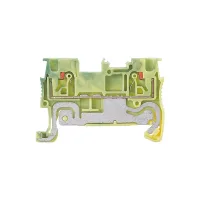
CPT-PE push-in protective earth terminal blocks provide yellow-green ground connections for NS35 rails. Single- and multi-level arrangements cover seventeen configurations with model-specific conductor ranges and outlines. Integrated test holes allow testing without removing conductors or bridges, and bridge wells support transverse connections.
Select the complete model, conductor range, rail-mounted height and associated end plate together. All models below use yellow-green PE identification. The numerical current and voltage ratings of feed-through terminal versions are separate from the specifications of these ground terminals.
Rigid and flexible conductor ranges are stated separately in mm². Dimensions are in mm: thickness, width, body height and height on the NS35 rail. AWG references remain separate from the metric ranges.
| Model | AWG | Rigid / flexible conductor in mm² | Thickness | Width | Body height | NS35 height |
|---|---|---|---|---|---|---|
| CPT-1.5PE | 26–14 | 0.2–1.5 /0.2–1.5 | 3.5 | 45 | 30.5 | 32 |
| CPT-1.5/2PE | 65.4 | 41.1 | 42.6 | |||
| CPT-1.5/1-2PE | 54.1 | 30.5 | 32 | |||
| CPT-1.5/2-2PE | 63.2 | |||||
| CPT-2.5PE | 26–12 | 0.2–4 /0.2–4 | 5.2 | 48.6 | 35.5 | 36.8 |
| CPT-2.5/2PE | 68.4 | 46.1 | 47.6 | |||
| CPT-2.5/1-2PE | 60.4 | 35.5 | 36.8 | |||
| CPT-2.5/2-2PE | 72.4 | |||||
| CPT-4PE | 24–10 | 0.2–6 /0.2–6 | 6.2 | 55.8 | 35.5 | 36.8 |
| CPT-4/2PE | 83.7 | 45.9 | 47.4 | |||
| CPT-4PE/1-2 | 66.4 | 35.5 | 36.8 | |||
| CPT-4PE/2-2 | 76.9 | 35.3 | ||||
| CPT-6PE | 20–8 | 0.5–10 /0.5–10 | 8.2 | 57 | 42.2 | 43.7 |
| CPT-6/1-2PE | 74.1 | |||||
| CPT-6PE/2-2 | 90.5 | |||||
| CPT-10PE | 20–6 | 0.5–16 /0.5–16 | 10.2 | 67.7 | 49.6 | 51.1 |
| CPT-16PE | 20–4 | 0.5–25 /0.5–25 | 12.2 | 75.4 | 52.6 | 54.1 |
CPT-4PE load selection depends on the maximum load capacity of a 6mm² rigid conductor. A numerical current value is unspecified. Numerical current and voltage ratings are not assigned to the other PE models in these tables.


| PE terminal model | End plate | Accessory group |
|---|---|---|
| CPT-1.5PE | D-CPT-1.5 | A |
| CPT-1.5/2PE | D-CPT-1.5/2 | |
| CPT-1.5/1-2PE | D-CPT-1.5/1-2 | |
| CPT-1.5/2-2PE | D-CPT-1.5/2-2 | |
| CPT-2.5PE | D-CPT-2.5 | B |
| CPT-2.5/2PE | D-CPT-2.5/2 | |
| CPT-2.5/1-2PE | D-CPT-2.5/1-2 | |
| CPT-2.5/2-2PE | D-CPT-2.5/2-2 | |
| CPT-4PE | D-CPT-4 | C |
| CPT-4/2PE | D-CPT-4/2 | |
| CPT-4PE/1-2 | D-CPT-4/1-2 | |
| CPT-4PE/2-2 | D-CPT-4/2-2 | |
| CPT-6PE | D-CPT-6 | D |
| CPT-6/1-2PE | D-CPT-6/1-2 | |
| CPT-6PE/2-2 | D-CPT-6/2-2 | |
| CPT-10PE | D-CPT-10 | E |
| CPT-16PE | D-CPT-16 | F |
| Group | Plug-in bridges | Screwdriver tip in mm | Flat marker | Marker bar | End clamp |
|---|---|---|---|---|---|
| A | CFBS2-3.5 CFBS3-3.5 CFBS10-3.5 | 0.4×2.5 | Not specified | ZB3 | E/UK3 |
| B | CFBS2-5 CFBS3-5 CFBS10-5 | 0.6×3.5 | ZBFM5 | ZB5 | |
| C | CFBS2-6 CFBS3-6 CFBS10-6 | ZBFM6 | ZB6 | ||
| D | CFBS2-8 CFBS3-8 CFBS4-8 CFBS5-8 CFBS10-8 | 0.8×4 | ZBFM8 | ZB8 | |
| E | CFBS2-10 CFBS5-10 | 0.6×3.5 | Not specified | ZB10 | |
| F | CFBS2-12 | 1×5.5 | ZB12 |
Plug-in bridges make transverse connections through the central bridge well; available pole counts depend on the listed group. Flat marking strips fit the outer marking groove and are described as 10 strips with 10 positions each. ZB marker bars provide horizontal or vertical characters in 10-position arrangements. E/UK3 end clamps secure the end of a terminal row and accept marking accessories.
