

| Part Number: | CMT | - | 2 | S | 2 | - | T1 |
|---|---|---|---|---|---|---|---|
| Explanation: |
Series CMT - Combined temperature control system with CME temperature modules and a CMG communication module |
Power Supply 2 - 24VAC/DC; AC frequency 50/60Hz |
Temperature Input K - K/E/J/L/T/R/S thermocouples |
Control Output 1 - Relay |
Module Combination T1 - One communication module plus one four-channel temperature module; 4 temperature channels |
CMT combines a CMG communication module with CME temperature control modules to form one coordinated system. Each temperature module in the T1–T4 assemblies has four channels. Select 4, 8, 12 or 16 independent temperature control channels and communicate with the assembly using Modbus TCP or Modbus RTU.
The four listed 24V models use universal thermocouple/resistance temperature inputs and SSR control outputs. The ordering guide also defines mains supply, dedicated input and other output options. Specify those options in the complete assembly code and confirm the matching component configuration.

| Field | Code | Meaning |
|---|---|---|
| Series | CMT | Combined temperature control module system |
| Supply | 2 | 24VAC/DC; AC frequency 50/60Hz |
| 4 | 100–240VAC, 50/60Hz | |
| A–Z letter combinations | Other or custom supply voltages | |
| Input | K | Thermocouples: K, E, J, L, T, R and S |
| P | Resistance temperature sensors: Pt100 and Cu50 | |
| A | 4–20mA input | |
| S | Universal thermocouple and resistance input: K, E, J, L, T, R, S, Pt100 and Cu50 | |
| Control output | 1 | Relay |
| 2 | SSR output | |
| A | 0–20mA or 4–20mA | |
| B | 0–5V or 1–5V | |
| A–Z letter combinations | Other or custom control output modes | |
| Combination | T1 | One communication module plus one four-channel temperature module: 4 temperature channels |
| T2 | One communication module plus two four-channel temperature modules: 8 temperature channels | |
| T3 | One communication module plus three four-channel temperature modules: 12 temperature channels | |
| T4 | One communication module plus four four-channel temperature modules: 16 temperature channels |
| Model | Supply | CME temperature modules | Temperature channels | Input | Output |
|---|---|---|---|---|---|
| CMT-2S2-T1 | 24VAC/DC; 50/60Hz for AC | 1 | 4 | K/E/J/L/T/R/S thermocouples; Pt100/Cu50 resistance sensors | SSR |
| CMT-2S2-T2 | 2 | 8 | |||
| CMT-2S2-T3 | 3 | 12 | |||
| CMT-2S2-T4 | 4 | 16 |
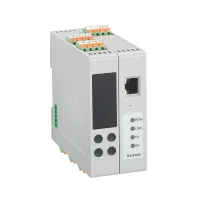
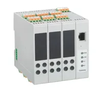
Each listed assembly includes one CMG communication module in addition to the temperature modules counted above. The four product photographs show the increasing module count, from one to four temperature modules beside the communication module.
| Assembly | Communication module | Temperature modules | Supply and function |
|---|---|---|---|
| CMT-4S2-T2 | CMG-TC-4NT2 | CME4-4S2/3T21 CME4-4S2/3T22 | 100–240VAC; 8 temperature channels; universal temperature input; SSR output |
| CMT-4S2-T4 | CMG-TC-4NT4 | CME4-4S2/3T41 CME4-4S2/3T42 CME4-4S2/3T43 CME4-4S2/3T44 | 100–240VAC; 16 temperature channels; universal temperature input; SSR output |
| CMT-2S2-T2 | CMG-TC-2NT2 | CME4-2S2/3T21 CME4-2S2/3T22 | 24VAC/DC; 8 temperature channels; universal temperature input; SSR output |
| CMT-2S2-T4 | CMG-TC-2NT4 | CME4-2S2/3T41 CME4-2S2/3T42 CME4-2S2/3T43 CME4-2S2/3T44 | 24VAC/DC; 16 temperature channels; universal temperature input; SSR output |
The component suffixes identify their assembly connection and position. Preserve the complete CME and CMG codes when specifying replacements or an assembled system. All four examples above accept K/E/J/L/T/R/S thermocouples and Pt100/Cu50 resistance sensors.

One CMG coordinates up to four CME temperature modules, allowing the host to treat the assembly as a single device for communication and control logic. Standard Modbus TCP and Modbus RTU are supported. Specify the host connection, channel count, temperature sensors, output type and supply before selecting the complete assembly.
The selection document provides model composition and communication topology. Use the applicable CME/CMG connection and operating documentation for terminal assignments, dimensions, settings and installation clearances. The official web listing identifies CE and TUV; obtain evidence applicable to the supplied configuration when required.
The manufacturer's use restrictions require specially designed products and written confirmation for high reliability energy systems, applications involving personal safety or major property risk, harsh or outdoor environments, fire or explosion risks, and military or aerospace use.
