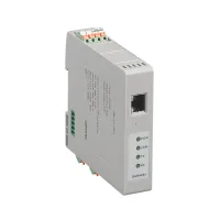
| Part Number: | CMG | - | TC | - | 2 | N | T1 |
|---|---|---|---|---|---|---|---|
| Explanation: |
Series CMG - Communication module for the CME modular temperature control system |
Communication Function TC - TCP communication; RJ45 Ethernet supports Modbus TCP |
Power Supply 2 - 24VAC/DC±20%; AC frequency 50/60Hz |
Interface Package N - One RJ45 Ethernet port plus one RS485 port; Modbus TCP over Ethernet and Modbus RTU over RS485 |
Supported Temperature Modules T1 - One four-channel CME module, 4 temperature channels |
CMG communication modules are designed to work with CME temperature control modules. They provide an RJ45 Ethernet interface with Modbus TCP and an RS485 interface with Modbus RTU. A host system can communicate with the CMG to read and control the working data of the associated temperature channels.
The CMG coordinates its connected temperature modules and organizes their data as one multi-channel temperature control assembly. T1 through T4 specify support for one to four four-channel CME modules, corresponding to 4, 8, 12 or 16 temperature channels. Choose the module capacity and supply version together; the CMG is the communication component of the assembly.

| Field | Codes and meaning |
|---|---|
| Series | CMG: communication module for the CME temperature control system |
| Function | TC: TCP communication |
| Supply | 2: 24VAC/DC; 4: 100–240VAC; A–Z letter combinations: other custom supply versions |
| Interface package | N: one RJ45 Ethernet port plus one RS485 communication port |
| Supported modules | T1: one four-channel CME module; T2: two; T3: three; T4: four |
| 100–240VAC model | 24VAC/DC model | Supported four-channel CME modules | Temperature channels in the specified assembly |
|---|---|---|---|
| CMG-TC-4NT1 | CMG-TC-2NT1 | 1 | 4 |
| CMG-TC-4NT2 | CMG-TC-2NT2 | 2 | 8 |
| CMG-TC-4NT3 | CMG-TC-2NT3 | 3 | 12 |
| CMG-TC-4NT4 | CMG-TC-2NT4 | 4 | 16 |
Every model in this table has the N port package, providing RJ45/Modbus TCP and RS485/Modbus RTU. The common enclosure photograph represents the range; the complete model specifies the supported temperature module count and power supply.
| Characteristic | Specified value |
|---|---|
| Mains supply version | 100–240VAC, 50/60Hz |
| 24V supply version | 24VAC/DC±20%; AC frequency 50/60Hz |
| Power consumption | No more than 7W |
| Ethernet port | RJ45; adaptive 10/100Mbps; Modbus TCP |
| RS485 port | Half duplex; Modbus RTU |
| RS485 baud rate choices | 4800, 9600, 19200, 38400 or 115200bps |
| Data retention with power removed | At least 10 years |
| Alarm relay output | 3A at 220VAC or 30VDC |
| Operating environment | 0°C to +50°C; 35–85%RH, without condensation |
| Storage environment | −25°C to +65°C; avoid freezing and condensation |
Select the CMG capacity for the intended number of four-channel CME modules, then specify the temperature modules' inputs, outputs and combination connection arrangement. The CMG manages the combined data presented to the host. The photographed front panel identifies POW, LINK, TX and RX indicators for power, link, transmission and reception.
Reserve space for the supply terminals, RS485 connection, Ethernet plug and access to the module assembly. The selection document does not provide enclosure dimensions, a network register map or detailed address settings. Use the applicable system documentation for those installation and commissioning details.
The official listing identifies CE and TUV for the range; obtain the evidence applicable to the ordered version when required for procurement. The manufacturer requires specially designed equipment and written confirmation for high reliability energy systems, applications involving personal safety or major property risk, harsh or outdoor environments, fire or explosion risks, and military or aerospace use.
