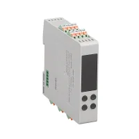
CME modules combine temperature input, PID control and local indication in a compact enclosure for rail installation. One, two and four-channel versions let a control cabinet handle several temperature loops without a separate panel instrument for each loop. Each channel has independent control parameters. Applications described for the range include packaging machinery, hot runners and production lines requiring heating or cooling control.
Choose the channel count, supply, sensor input and control output as a complete configuration. R versions provide RS485 with Modbus RTU for connection to a PLC or operator display; N versions have no communication interface specified. Side quick connection options support multi-module assemblies, with separate codes for the connection side, assembly size and module position.

| Field | Codes and meaning | Condition |
|---|---|---|
| Series | CME: standard modular temperature controller; CMH: high precision version in the wider guide | The full model and ±0.5%FS data below describe CME, not a separate CMH accuracy specification. |
| Channels | 1: one; 2: two; 4: four | The digit after CME specifies the number of temperature control channels. |
| Supply | 2: 24VAC/DC; 4: 100–240VAC; A–Z letter combinations: other custom supplies | AC frequency is 50/60Hz. The 24V option is not the 24–48V range used by some other controller families. |
| Input | K: thermocouples K/E/J/L/T/R/S; P: Pt100 or Cu50 RTD; A: 4–20mA input; S: thermocouple and RTD input capability | Use the actual ordered input hardware and configure the sensor type. The A input option is a process signal rather than a listed thermocouple range. |
| Control output | 1: relay; 2: SSR drive; A: 0–20mA or 4–20mA; B: 0–5V or 1–5V; letter combinations: other custom output versions | All thirteen complete common models below use SSR drive output code 2. |
| Communication | N: no communication; R: RS485 | Modbus RTU is specified for the RS485 interface. |
| Side quick connection | No code: absent; 1: left input; 2: right output; 3: left input and right output | Choose the connection arrangement for the module's place in an assembly. |
| Combination mode | No code: standalone; T1: one communication module plus one four-channel temperature module; T2: one plus two; T3: one plus three; T4: one plus four | The stated four-channel assemblies provide 4, 8, 12 or 16 temperature channels respectively. |
| Combination unit | No code: standalone; 1/2/3/4: temperature module position in the combination | This position code is separate from the channel count and assembly size. |
| Model | Channels | Supply | Input capability | Control output | Communication |
|---|---|---|---|---|---|
| CME1-4K2R | 1 | 100–240VAC | Thermocouples K/E/J/L/T/R/S | SSR drive | RS485, Modbus RTU |
| CME2-4K2R | 2 | ||||
| CME4-4K2R | 4 | ||||
| CME1-4S2R | 1 | 100–240VAC | Thermocouples and Pt100/Cu50 RTDs | ||
| CME2-4S2R | 2 | ||||
| CME4-4S2R | 4 | ||||
| CME1-2S2R | 1 | 24VAC/DC | Thermocouples and Pt100/Cu50 RTDs | ||
| CME2-2S2R | 2 | ||||
| CME4-2S2R | 4 | ||||
| CME2-4P2R | 2 | 100–240VAC | Pt100/Cu50 RTDs | ||
| CME4-4P2R | 4 | ||||
| CME2-2S2N | 2 | 24VAC/DC | Thermocouples and Pt100/Cu50 RTDs | None | |
| CME4-2S2N | 4 |
The product photographs are representative of the enclosure; identical appearance does not establish the installed channel count or interface. Match the complete model code to the supply and sensor configuration. The P and N selections are additional complete models shown on the official product pages alongside the PDF common-model selections.
| Characteristic | Specified value or condition |
|---|---|
| Supply | 100–240VAC or 24VAC/DC by ordered code; AC frequency 50/60Hz |
| Power consumption | No more than 5VA |
| Operating environment | 0°C to +50°C; 35–85%RH, without condensation |
| Storage environment | −25°C to +65°C; avoid freezing and condensation |
| Resolution / detection accuracy | 1°C or 0.1°C, adjustable / ±0.5%FS |
| Connection / memory | Terminal block / nonvolatile memory |
| SSR logic drive, output code 2 | ON: 12VDC; OFF: below 0.5VDC; maximum current 30mA |
| Relay output, when a relay version is ordered | 3A at 220VAC or 30VDC |
| Catalog documentation reference | CE, EN61010-1; supporting document available from the CNTD representative |
The SSR output is a drive signal for an external switching device. Its 30mA limit is not a heater load rating. The relay rating applies to the relay output version and is not the output interface fitted to the common SSR models.

| Input group | Sensor | Temperature range |
|---|---|---|
| Thermocouple | K | −60°C to +1200°C |
| E | −60°C to +950°C | |
| J | −60°C to +1150°C | |
| L | 0°C to +800°C | |
| T | −60°C to +350°C | |
| R | 0°C to +1700°C | |
| S | 0°C to +1600°C | |
| RTD | Pt100 | −60°C to +600°C |
| Cu50 | −60°C to +150°C |

| Display, indicator or key | Meaning or action |
|---|---|
| PV / SV | Measured value and status prompts / setpoint and parameter values |
| °C indicator | Lit in Celsius indication; off for Fahrenheit indication |
| CH1–CH4 | Selected temperature control channel indication |
| AT / COM / OUT | AT is lit during tuning; COM flashes during normal RS485 communication; OUT is lit during main output operation. |
| ALM / ERR | ALM is lit when the measured temperature is above the set temperature; ERR indicates a fault requiring the displayed error information. |
| Up / down | Increase / decrease a value or change the channel being viewed. |
| Left | Select the digit being adjusted; press and hold to enter or leave tuning. |
| Left plus up / left plus down | Press and hold to leave stop mode / enter stop mode. |
| M | Short press to enter settings or switch parameters; hold for 3s to enter the menu, or return to its parent level according to the current menu state. |
Side quick sockets allow compatible modules to be joined into larger temperature control assemblies. The guide separates the connection side, combination mode and individual module position so that a left, right or intermediate unit can be specified correctly. Select the rail layout and allow wiring and service access around the terminals; this selection document does not provide a dimensional outline or a rail width specification.
The manufacturer requires a specially designed version and written confirmation for high reliability energy systems, applications involving personal safety or major property risk, harsh or outdoor environments, fire or explosion risks, and military or aerospace applications.
