
CLW2-20 modular cam switches provide a 20A conventional thermal-current rating and a choice of detent, spring-return, illuminated and key-operated mechanisms. Their rotary contact programs cover circuit changeover, instrument selection, distribution controls and motor switching. Choose the contact schedule, indexing angle, handle, mounting form and panel wording as a complete configuration.
Standard detent arrangements support up to twelve sections; eight or fewer are recommended. Spring-return arrangements support up to ten. The D illuminated detent drawing specifies eleven sections maximum. Available indexing steps are 30°, 45°, 60° and 90°; contact logic and the number of sections can restrict the operating range.
| Field | Code | Selection meaning |
|---|---|---|
| Design family | CLW2 | Modular cam switch |
| Thermal current | 20 | Ith20A |
| Mechanical function | Omitted | Conventional version |
| C | Single-hole mounting | |
| CP | Single-hole mounting with label, default label arrangement | |
| D | Illuminated version | |
| M1 | Large mounting plate; 48×48mm mounting-hole spacing, applicable to 20A and 25A versions | |
| P | Label version, default label arrangement | |
| S | Three-hole mounting | |
| U | Single-hole mounting without front plate | |
| UY1 | Single-hole mounting without front plate, key-operated handle | |
| G1 | G1 handle arrangement | |
| G2 | G2 handle arrangement | |
| Y1 | Key-operated handle | |
| Y1P | Key-operated handle with label | |
| Position program | Example: 6KC | Step angle and start/end positions; this example gives −60°, 0°, 60° |
| Contact program | Example: 202 | Contact states at each position; specify a contact diagram for special programs |
| Sections | 1–12; example: 3 | Prefer eight or fewer; observe the selected mechanism's limit |
| Handle style | A, A1, AD, B, C, C1, G1, G2 | Match the illustrated handle and mounting version; the ordering example uses Ar |
| Handle color | K / C / R | Black / blue / red |
| Panel print | Example: B14; special print: P | Omitting the print code uses the standard wording for the selected contact program |


The first position-code character selects 3=30°, 4=45°, 6=60° or 9=90°. The following two letters identify the starting and ending positions on the appropriate circle, clockwise. A is the 0° reference; O is a letter, not a numeric zero. For continuous 360° rotation, the start and end letters are the same.
| Example | Indexing step | Position sequence |
|---|---|---|
| 3KC | 30° | K, O, A, B, C |
| 4OB | 45° | O, A, B |
| 6KE | 60° | K, A, C, E |
| 9GC | 90° | G, A, C |
| 3JJ | 30° | Twelve positions over 360°, starting at −90°, without an end stop |

Arrows below show spring-return directions; commas separate positions without a return arrow between them. Y means available; Y* means available with three sections or fewer.
| Return code | Angles and return directions | Availability |
|---|---|---|
| A1 | 0° ← 30° | Y* |
| A2 | 0° ← 45° | Y |
| A3 | −45° ← 45° | Y |
| A4 | −45° ← 0° | Y |
| A5 | 0° ← 90° | Y |
| B1 | −30° → 0° ← 30° | Y* |
| B2 | −45° → 0° ← 45° | Y |
| B3 | −60° → −30° → 0° ← 30° ← 60° | Y* |
| B4 | −90°, −45°, 0°, 45° ← 90° | Y |
| B5 | −90°, −45°, 0° ← 45° | Y |
| B6 | −90° → −60° → −30° → 0° ← 30° ← 60° ← 90° | Y* |
| B7 | −90° → −45°, 0°, 45°, 90°, 135° | Y |
| B8 | −90° → −45°, 0°, 45°, 90° | Y |
| B9 | −45° → 0°, 45°, 90°, 135° | Y |
| B10 | −45° → 0°, 45°, 90°, 135°, 180° | Y |
| B11 | −45° → 0° ← 45° ← 90° | Y |
| BA | −90° → −45° → 0° ← 45° ← 90° | Y |
| BA1 | −45° → 0° → 45° ← 90° ← 135° | Y |
| BC | −45° → 0° ← 45° | Y |
| D4 | 0° ← 45° ← 90° | Y |
| Z1 | −135° → −90°, 0° ← 45° | Y |
| Z2 | −45° → 0°, 90° ← 135° | Y |
| ZA | −90° → −45°, 0°, 45° ← 90° | Y |
| ZB | −90° → −45°, 0°, 45° | Y |
| ZC | −45°, 0°, 45° ← 90° | Y |
| ZD | −90°, 0° ← 45° | Y |
| ZE | 0°, 45° ← 90° | Y |
| ZF | −45°, 0° ← 45° | Y |
| ZG | −45° → 0°, 45° | Y |
| ZK | −45° → 0°, 45°, 90° | Y |
| ZK1 | −45° → 0°, 45°, 90°, 135° | Y |
| W | −120° → −90°, 0° ← 30° | Y* |
| WA | −90°, 0° ← 30° | Y* |
| WB | −30° → 0°, 90° | Y* |
| WC | 0°, 90° ← 120° | Y* |
| WR | −120° → −90°, 0°, 90° ← 120° | Y* |
| WS | −90°, 0°, 90° ← 120° | Y* |
| WT | −120° → −90°, 0°, 90° | Y* |
| WU | −90°, −30° → 0° ← 30° | Y* |
| WV | −90°, 0° ← 30°, 90° | Y* |
| Group | Parameter | Value |
|---|---|---|
| Electrical and mechanical | Referenced standard | GB/T14048.5 |
| Conventional thermal current | 20A | |
| Rated insulation voltage | 690VAC | |
| Impulse withstand voltage | 4kV | |
| Frequency | 50Hz | |
| Mechanical life | 500000 operations | |
| Electrical life | AC300000; DC200000 operations | |
| Operating frequency | 300 operations/hour | |
| Shock resistance | 50g, 11ms, half-sine waveform | |
| Vibration resistance | 10–500Hz, 5g | |
| Operating conditions | Ambient temperature | −25°C to +55°C |
| Humidity | ≤90%RH | |
| Pollution degree | 3 | |
| Installation category | III | |
| Storage/transport temperature | −40°C to +80°C | |
| Protection | IP65 at the working face |
Application voltage limits are 380VAC and 220VDC. The 20A thermal-current rating is separate from the operating currents for each utilization category.
| Utilization category | 24V | 48V | 110V | 220V | 380V |
|---|---|---|---|---|---|
| AC-15 | — | — | 8A | 4A | 3A |
| DC-13 | 4A | 2.4A | 1.1A | 0.55A | — |
A dash denotes an unspecified rating.
Dimensions below are in mm; n is the number of contact sections. Detent and spring-return rear depths are separate. Prefer eight or fewer sections, within the selected mechanism's maximum. All illustrated indexing steps are 30°, 45°, 60° and 90°.
| Version | Handle / front size | Front projection | Rear depth, detent / return | Panel thickness | Mounting |
|---|---|---|---|---|---|
| CLW2-20 | A/A1/B/C/C1; 48×48 | 29 | 23.5+10n / 38.8+10n | 1–3 | Four Ø4.5 holes, 36±0.20 square; center Ø10 |
| CLW2-20P | A/A1/B/C/C1; 48×65 label plate | ||||
| CLW2-20D | A/A1/B/C/C1; 48×65 illuminated plate | 23.5+10n detent; return depth not specified | Four Ø4.5 holes, 36±0.20 square; center Ø10; lamp opening 40mm +0.20/0 ×15.8mm +0.15/0, offset 32.1±0.15 | ||
| CLW2-20M1 | AD only; 64×64 | 33.5 | 24+10n / 39.3+10n | Four Ø4.5 holes, 48±0.20 square; center Ø10 | |
| CLW2-20G1 | G1; 48×48 | 34.7 | 23.5+10n / 38.8+10n | 36±0.20 square mounting; Ø10 center | |
| CLW2-20G2 | G2; 64×64 | 40.5 | 24+10n / 39.3+10n | Four Ø4.5 holes, 48±0.20 square; Ø10 center | |
| CLW2-20S | A/A1/B/C/C1; 48×48 | 29 | 23.5+10n / 38.8+10n | Ø10 center and two Ø4.5 holes, 30±0.20 spacing | |
| CLW2-20C | A/A1/B/C/C1; 48×48 | 27.4 | 46.7+10n / 62+10n | 1–4 | Keyed Ø22.3mm +0.40/0 cutout; overall keyed height 24.1mm +0.40/0, key width 3.2mm +0.20/0, R0.8 |
| CLW2-20CP | A/A1/B/C/C1; 48×65 label plate | ||||
| CLW2-20U | A/C; no plate, Ø43 base, 23 handle half-height | ||||
| CLW2-20Y1 | Key; 48×48 | 15.3 | |||
| CLW2-20Y1P | Key; 48×65 label plate | ||||
| CLW2-20UY1 | Key; no plate, Ø43 base |


Each section contains two contact pairs. The tables list closed contacts; unlisted pairs are open. An on/off program opens all pairs at 0 and closes both pair groups at 1. Changeover closes the first group at position 1 and the second at position 2; a center-off program adds an all-open 0 position between them. Bridged programs add links between even terminals 2–4, 6–8, 10–12 and the corresponding even terminals of later sections.
| Sections | On/off | Two-position independent | Two-position bridged | Center-off independent | Center-off bridged |
|---|---|---|---|---|---|
| 1 | 02/1 | 11/1 | 11J/1 | 101/1 | 101J/1 |
| 2 | 04/2 | 22/2 | 22J/2 | 202/2 | 202J/2 |
| 3 | 06/3 | 33/3 | 33J/3 | 303/3 | 303J/3 |
| 4 | 08/4 | 44/4 | 44J/4 | 404/4 | 404J/4 |
| 5 | 0A/5 | 55/5 | 55J/5 | 505/5 | 505J/5 |
| 6 | 0C/6 | 66/6 | 66J/6 | 606/6 | 606J/6 |
| 7 | 0E/7 | 77/7 | 77J/7 | 707/7 | 707J/7 |
| 8 | 0G/8 | 88/8 | 88J/8 | 808/8 | 808J/8 |
| 9 | 0I/9 | 99/9 | 99J/9 | 909/9 | 909J/9 |
| 10 | 0K/10 | AA/10 | AAJ/10 | A0A/10 | A0AJ/10 |
| Sections | Position 1 pair group | Position 2 pair group |
|---|---|---|
| 1 | 1–2 | 3–4 |
| 2 | 1–2, 5–6 | 3–4, 7–8 |
| 3 | 1–2, 5–6, 9–10 | 3–4, 7–8, 11–12 |
| 4 | 1–2, 5–6, 9–10, 13–14 | 3–4, 7–8, 11–12, 15–16 |
| 5 | 1–2, 5–6, 9–10, 13–14, 17–18 | 3–4, 7–8, 11–12, 15–16, 19–20 |
| 6 | 1–2, 5–6, 9–10, 13–14, 17–18, 21–22 | 3–4, 7–8, 11–12, 15–16, 19–20, 23–24 |
| 7 | 1–2, 5–6, 9–10, 13–14, 17–18, 21–22, 25–26 | 3–4, 7–8, 11–12, 15–16, 19–20, 23–24, 27–28 |
| 8 | 1–2, 5–6, 9–10, 13–14, 17–18, 21–22, 25–26, 29–30 | 3–4, 7–8, 11–12, 15–16, 19–20, 23–24, 27–28, 31–32 |
| 9 | 1–2, 5–6, 9–10, 13–14, 17–18, 21–22, 25–26, 29–30, 33–34 | 3–4, 7–8, 11–12, 15–16, 19–20, 23–24, 27–28, 31–32, 35–36 |
| 10 | 1–2, 5–6, 9–10, 13–14, 17–18, 21–22, 25–26, 29–30, 33–34, 37–38 | 3–4, 7–8, 11–12, 15–16, 19–20, 23–24, 27–28, 31–32, 35–36, 39–40 |
| Complete example | Function | Angles | Panel labels |
|---|---|---|---|
| CLW2-20-4AB-06/3 | Three-section on/off | 0°, 45° | 0, 1 |
| CLW2-20-9OB-33/3 | Three-section independent changeover | −45°, 45° | 1, 2 |
| CLW2-20-6OB-33J/3 | Three-section bridged changeover | −30°, 30° | 1, 2 |
| CLW2-20-4OB-303/3 | Three-section independent center-off | −45°, 0°, 45° | 1, 0, 2 |
| CLW2-20-4OB-404J/4 | Four-section bridged center-off | −45°, 0°, 45° | 1, 0, 2 |


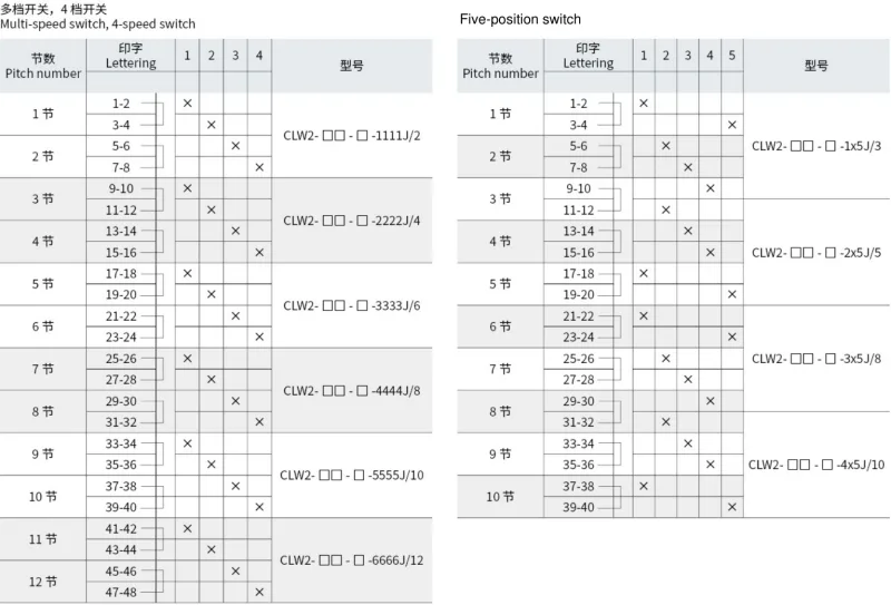
These programs include the common-terminal bridges shown in the drawings. Each row states the closed contacts at every operating position; all other fitted pairs are open.
| Three-position program | Position 1 | Position 2 | Position 3 |
|---|---|---|---|
| 111J/1 | 1–2 | 3–4 | None |
| 212J/2 | 1–2, 7–8 | 3–4 | 5–6 |
| 313J/3 | 1–2, 7–8 | 3–4, 9–10 | 5–6, 11–12 |
| 414J/4 | 1–2, 7–8, 13–14 | 3–4, 9–10, 15–16 | 5–6, 11–12 |
| 515J/5 | 1–2, 7–8, 13–14, 19–20 | 3–4, 9–10, 15–16 | 5–6, 11–12, 17–18 |
| 616J/6 | 1–2, 7–8, 13–14, 19–20 | 3–4, 9–10, 15–16, 21–22 | 5–6, 11–12, 17–18, 23–24 |
| 717J/7 | 1–2, 7–8, 13–14, 19–20, 25–26 | 3–4, 9–10, 15–16, 21–22, 27–28 | 5–6, 11–12, 17–18, 23–24 |
| 818J/8 | 1–2, 7–8, 13–14, 19–20, 25–26, 31–32 | 3–4, 9–10, 15–16, 21–22, 27–28 | 5–6, 11–12, 17–18, 23–24, 29–30 |
| 919J/9 | 1–2, 7–8, 13–14, 19–20, 25–26, 31–32 | 3–4, 9–10, 15–16, 21–22, 27–28, 33–34 | 5–6, 11–12, 17–18, 23–24, 29–30, 35–36 |
| Four-position program | Sections | Position 1 | Position 2 | Position 3 | Position 4 |
|---|---|---|---|---|---|
| 1111J/2 | 2 | 1–2 | 3–4 | 5–6 | 7–8 |
| 2222J/4 | 4 | 1–2, 9–10 | 3–4, 11–12 | 5–6, 13–14 | 7–8, 15–16 |
| 3333J/6 | 6 | 1–2, 9–10, 17–18 | 3–4, 11–12, 19–20 | 5–6, 13–14, 21–22 | 7–8, 15–16, 23–24 |
| 4444J/8 | 8 | 1–2, 9–10, 17–18, 25–26 | 3–4, 11–12, 19–20, 27–28 | 5–6, 13–14, 21–22, 29–30 | 7–8, 15–16, 23–24, 31–32 |
| 5555J/10 | 10 | 1–2, 9–10, 17–18, 25–26, 33–34 | 3–4, 11–12, 19–20, 27–28, 35–36 | 5–6, 13–14, 21–22, 29–30, 37–38 | 7–8, 15–16, 23–24, 31–32, 39–40 |
| 6666J/12 | 12 | 1–2, 9–10, 17–18, 25–26, 33–34, 41–42 | 3–4, 11–12, 19–20, 27–28, 35–36, 43–44 | 5–6, 13–14, 21–22, 29–30, 37–38, 45–46 | 7–8, 15–16, 23–24, 31–32, 39–40, 47–48 |
| Five-position program | Sections | Applicable terminal pairs |
|---|---|---|
| 1x5J/3 | 3 | 1–2 through 11–12 |
| 2x5J/5 | 5 | 1–2 through 19–20 |
| 3x5J/8 | 8 | 1–2 through 31–32 |
| 4x5J/10 | 10 | 1–2 through 39–40 |
For each five-position program, use only the pairs within its terminal range from the following complete schedule.
| Operating position | Closed terminal pairs |
|---|---|
| 1 | 1–2, 17–18, 21–22, 37–38 |
| 2 | 5–6, 11–12, 25–26, 31–32 |
| 3 | 7–8, 13–14, 27–28, 33–34 |
| 4 | 9–10, 15–16, 29–30, 35–36 |
| 5 | 3–4, 19–20, 23–24, 39–40 |
A standard contact code identifies a defined schedule. A custom × suffix requires a separate contact diagram; the suffix alone does not define its switching states.
| Program | Position 1 closed pairs | Position 2 closed pairs | Position 3 closed pairs |
|---|---|---|---|
| 424/3 | 1–2, 3–4, 5–6, 7–8 | 9–10, 11–12 | 1–2, 3–4, 5–6, 7–8 |
| 424×/3, illustrated custom schedule | 1–2, 7–8, 11–12 | 5–6, 11–12 | 1–2, 3–4, 5–6, 7–8, 9–10 |
The following schedules list closed terminal pairs at each panel position. Unlisted contacts are open. Retain the internal and external links shown in the corresponding wiring drawing.
| Model | Measurement arrangement | Position, angle → closed pairs |
|---|---|---|
| CLW2-20-YH1/3 | Three phase-to-neutral voltages; N connection and off position |
0, 0° → None
A, 90° → 1–2, 9–10 B, 180° → 5–6, 9–10 C, 270° → 3–4, 9–10 |
| CLW2-20-YH2/3 | Three line voltages; off position |
0, 0° → None
AB, 90° → 1–2, 7–8 BC, 180° → 1–2, 11–12 CA, 270° → 5–6, 11–12 |
| CLW2-20-YH3/3 | Three line voltages; no N; off position |
0, 0° → None
AB, 90° → 1–2, 7–8 BC, 180° → 5–6, 11–12 CA, 270° → 3–4, 9–10 |
| CLW2-20-YH4/2 | Three line-voltage selections; no off position; A/B/C panel marks |
A, −90° → 1–2, 7–8
B, 0° → 1–2, 3–4 C, 90° → 3–4, 5–6 |
| CLW2-20-YH12/2 | Three line voltages; no N; off position |
0, 0° → None
AB, 90° → 3–4, 5–6 BC, 180° → 5–6, 7–8 CA, 270° → 1–2, 7–8 |
| CLW2-20-YH13/2 | Three phase-to-neutral voltages; N connection; no off position; panel references A72/B100 |
A, 90° → 1–2, 7–8
B, 180° → 3–4, 7–8 C, 270° → 5–6, 7–8 |
| CLW2-20-YH22/3 | Three line voltages; no N; off position; panel references A75/B103 |
0, 0° → None
AB, 90° → 1–2, 7–8 BC, 180° → 5–6, 11–12 CA, 270° → 3–4, 9–10 |
| CLW2-20-YH5/4 | Three line and three phase-to-neutral voltages; N connection and off position |
CA, −135° → 5–6, 11–12
BC, −90° → 1–2, 15–16 AB, −45° → 3–4, 11–12 0, 0° → None AN, 45° → 7–8, 9–10 BN, 90° → 3–4, 13–14 CN, 135° → 1–2, 9–10 |
| CLW2-20-YH6/4 | Three line voltages from each of two supplies; off position |
Supply 1 CA, −135° → 3–4, 11–12
Supply 1 BC, −90° → 7–8, 15–16 Supply 1 AB, −45° → 3–4, 15–16 0, 0° → None Supply 2 AB, 45° → 1–2, 9–10 Supply 2 BC, 90° → 5–6, 13–14 Supply 2 CA, 135° → 1–2, 13–14 |
| CLW2-20-YH8/4 | Three line voltages and one phase-to-neutral voltage; N connection and off position |
CA, −135° → 5–6, 11–12
BC, −90° → 1–2, 15–16 AB, −45° → 3–4, 11–12 0, 0° → None AN, 45° → 7–8, 9–10 |


Use the current-transformer connections and shorting contacts shown for the selected program. A panel position marked 0 can retain closed shorting contacts; it is not an all-open state.
| Model | Arrangement | Position, angle → closed pairs |
|---|---|---|
| CLW2-20-LH1/2 | Two CTs; no N; 0/A/B/C selection |
0, 0° → 1–2, 5–6
A, 90° → 3–4, 5–6 B, 180° → 3–4, 7–8 C, 270° → 1–2, 7–8 |
| CLW2-20-LH2/4 | Three CTs and N; N/A/B/C selection |
N, 0° → 1–2, 3–4, 5–6, 15–16
A, 90° → 1–2, 5–6, 7–8, 11–12 B, 180° → 1–2, 3–4, 7–8, 13–14 C, 270° → 3–4, 5–6, 7–8, 9–10 |
| CLW2-20-LH3/4 | Three CTs; no N; 0/A/B/C selection |
0, 0° → 1–2, 5–6, 7–8
A, 90° → 1–2, 7–8, 13–14 B, 180° → 5–6, 7–8, 9–10 C, 270° → 1–2, 5–6, 15–16 |

Six stages distinguish the operating history as well as the handle angle. Keep the two 0° states and the two −90° states separate. The closing and tripping positions return in the directions shown in the drawings.
| Stage | Panel meaning | Direction | Angle |
|---|---|---|---|
| T | After trip | ← | −90° |
| PC | Pre-close | ↑ | 0° |
| C | Close | ↗ | 45°, returning |
| CA | After close | ↑ | 0° |
| PT | Pre-trip | ← | −90° |
| TR | Trip | ↙ | −135°, returning |
| Model | Closed pairs at each stage | Replacement reference |
|---|---|---|
| CLW2-20-ZJ/1a.4.6a.40.20/7 |
T: 2–4, 11–10, 15–14, 20–18
PC: 1–3, 9–10, 13–14, 17–18 C: 5–8, 9–12, 13–16, 17–19 CA: 1–3, 9–10, 13–16, 17–19 PT: 2–4, 11–10, 13–14, 17–18 TR: 6–7, 11–10, 15–14, 20–18 |
CLW2-20-Z-1a.4.6a.40.20/F8 |
| CLW2-20-Z/49.6781/8 |
T: 3–4, 15–16, 23–24, 31–32
PC: 1–2, 9–10, 21–22, 29–30 C: 5–6, 13–14, 25–26, 27–28 CA: 1–2, 9–10, 25–26, 27–28 PT: 3–4, 15–16, 21–22, 29–30 TR: 7–8, 15–16, 17–18, 23–24, 31–32 |
CLW2-20-Z-1a.4.6a.40.20/F8 |
| CLW2-20-Z/1a.4.20/4 |
T: 3–4, 13–14
PC: 1–2, 11–12 C: 5–6, 9–10 CA: 1–2, 9–10 PT: 3–4, 11–12 TR: 7–8, 13–14 |
CLW2-20-Z-1a.20/F8 |
| CLW2-20-Z/1a.4.6a.40.20/5 |
T: 3–4, 11–12, 13–14, 19–20
PC: 1–2, 9–10, 13–14 C: 5–6, 9–10, 15–16, 17–18 CA: 1–2, 9–10, 15–16, 17–18 PT: 3–4, 11–12, 13–14 TR: 7–8, 11–12, 13–14, 19–20 |
CLW2-20-Z-1a.4.6a.40.20/F8 |
| CLW2-20-ZJ/1a.4.6a.20/6 |
T: 2–4, 11–10, 16–14
PC: 1–3, 9–10, 13–14 C: 5–8, 9–12, 13–15 CA: 1–3, 9–10, 13–15 PT: 2–4, 11–10, 13–14 TR: 6–7, 11–10, 16–14 |
CLW2-20-Z-1a.4.6a.20/F8 |

| Model | Cabinet function | Positions and angles |
|---|---|---|
| CLW2-20-3OI-21-9/6 | Eight-stage main cabinet | Auto−30°; 0–8 from 0° to 240°, 30° steps |
| CLW2-20-3OG-21-7/5 | Six-stage main cabinet | Auto−30°; 0–6 from 0° to 180°, 30° steps |
| CLW2-20-3OK-21-AC/7 | Ten-stage main cabinet | Auto−30°; 0–10 from 0° to 300°, 30° steps |
| CLW2-20-3JF-0-8/4 | Eight-stage auxiliary cabinet | 0–8 from −90° to 150°, 30° steps |
| CLW2-20-3JD-0-6/3 | Six-stage auxiliary cabinet | 0–6 from −90° to 90°, 30° steps |
| CLW2-20-3JH-0-A/5 | Ten-stage auxiliary cabinet | 0–10 from −90° to 210°, 30° steps |
O in 3OI, 3OG and 3OK is the −30° position letter. All main-cabinet contacts are open in Auto. Below, None means a fitted pair remains open; Not fitted is outside the program's contact count.
| Contact pair | Main 8-stage: closed stages | Main 6-stage: closed stages | Main 10-stage: closed stages |
|---|---|---|---|
| 1–2 | 1–8 | 1–6 | 1–10 |
| 3–4 | 0 | 0 | 0 |
| 5–6 | 0 | 0 | 0 |
| 7–8 | 1–8 | 1–6 | 1–10 |
| 9–10 | 2–8 | 2–6 | 2–10 |
| 11–12 | 3–8 | 3–6 | 3–10 |
| 13–14 | 4–8 | 4–6 | 4–10 |
| 15–16 | 5–8 | 5–6 | 5–10 |
| 17–18 | 6–8 | 6 | 6–10 |
| 19–20 | 7–8 | None | 7–10 |
| 21–22 | 8 | Not fitted | 8–10 |
| 23–24 | None | Not fitted | 9–10 |
| 25–26 | Not fitted | Not fitted | 10 |
| 27–28 | Not fitted | Not fitted | 10 |
| Contact pair | Auxiliary 8-stage: closed stages | Auxiliary 6-stage: closed stages | Auxiliary 10-stage: closed stages |
|---|---|---|---|
| 1–2 | 1–8 | 1–6 | 1–10 |
| 3–4 | 2–8 | 2–6 | 2–10 |
| 5–6 | 3–8 | 3–6 | 3–10 |
| 7–8 | 4–8 | 4–6 | 4–10 |
| 9–10 | 5–8 | 5–6 | 5–10 |
| 11–12 | 6–8 | 6 | 6–10 |
| 13–14 | 7–8 | Not fitted | 7–10 |
| 15–16 | 8 | Not fitted | 8–10 |
| 17–18 | Not fitted | Not fitted | 9–10 |
| 19–20 | Not fitted | Not fitted | 10 |
All auxiliary-cabinet pairs are open at stage 0. The ten-stage main-cabinet schedule closes both 25–26 and 27–28 at stage 10.

| Use code | Application |
|---|---|
| Q | Direct starting of a squirrel-cage motor |
| N | Forward/reverse starting |
| S | Two-speed motor starting and speed selection |
| XS | Star/delta starting |
The motor-use ordering fields specify thermal current, use code and motor power in kW, followed by the program's section and option fields. In these examples, 3 denotes 3kW and 1.2 denotes 1.2kW.
| Model | Application | Position, angle → closed pairs |
|---|---|---|
| CLW2-20-Q3/2 | Direct starting; switching off during operation |
OFF, 0° → None
ON, 45° → 1–2, 3–4, 5–6 |
| CLW2-20-N1.2/3 | Starting, reversing and reverse-current braking |
1, −45° → 3–4, 5–6, 9–10, 11–12
0, 0° → None 2, 45° → 1–2, 7–8, 9–10, 11–12 |
| CLW2-20-S3/4 | Two-speed motor starting and speed selection |
1, −45° → 1–2, 5–6, 7–8, 11–12, 13–14
0, 0° → None 2, 45° → 1–2, 3–4, 5–6, 9–10, 13–14, 15–16 |

Select a print code for both its wording and its physical layout. The English equivalents below identify the labels; use the illustrations for label locations and return arrows. Special printing uses P. Omitting a print code retains the default printing for the selected contact program.
| Print-code group | Layout angle | Content |
|---|---|---|
| A1–A22 | 30° | Worded operating and metering plates |
| B1–B59 | 45° | Worded operating, distribution and metering plates |
| C1–C18 | 60° | Worded operating plates |
| D1–D22 | 90° | Worded operating and metering plates |
| E1–E8 | 22.5° reference layouts | Numeric and Auto/Stop/Manual plates |
| F1–F17 | 30° | Numeric plates |
| G1–G29 | 45° | Numeric plates |
| H1–H14 | 60° | Numeric plates |
| I1–I11 | 90° | Numeric plates |
The E-series references describe printed layouts; they do not establish a 22.5° standard indexing mechanism for CLW2-20.
| Print code | English wording / symbols |
|---|---|
| A1 / B1 | Raise / 0 / Lower |
| A2 / B2 | Start / 0 / Stop |
| A3 / B3 | Trip / Stop / Close |
| A4 / B4 | Trip / 0 / Close |
| A5 / B5 | Off / 0 / On |
| A6 / B6 | Remote / Stop / Local |
| A7 / B7 | Increase speed / 0 / Decrease speed |
| A8 / B8 | Trip / Disconnect / Close |
| A9 / B9 | Open / 0 / Close |
| A10 / B10 | Close / 0 / Trip |
| A11 / B11 | Trip / 0 / Close |
| A12 | OFF / ON |
| A13 | Trip / 0 / Close |
| A14 | Auto / 0 / Manual |
| A15 | Raise voltage / Stop / Lower voltage |
| A16 | On / Stop / Off |
| A17 | Close / 0 / Trip |
| A18 | Decrease speed / Stop / Increase speed |
| A19 | AB, BC, CA, 0, A, B, C |
| A20 | Auto / Stop / Manual / 2–6 |
| A21 | Auto / Stop / Manual / 2–8 |
| A22 | Auto / Stop / Manual / 2–10 |
| B12 | Remote / Local / Trip / Close, arranged as illustrated |
| B13 | Remote / After trip / After close / Trip / Close |
| B14 / B15 / B16 | Pre-close / After close / Close / Pre-trip / After trip / Trip; three layouts |
| B17 | Stop / Start |
| B18 | On / Off |
| B19 | Manual / Auto |
| B20 | Insert / Withdraw |
| B21 | Working / Test |
| B22 | Disconnect / Connect |
| B23 | Local / Remote |
| B24 | Switch cabinet / Operator station |
| B25 | Withdraw / Insert |
| B26 | Manual / Auto |
| B27 | Remote / Local |
| B28 | Disconnect / Connect |
| B29 | Auto / Standby |
| B30 | Stop / Start |
| B31 | Field / Remote |
| B32 | Remote / Field |
| B33 | Manual / Remote control |
| B34 | Withdraw / Insert |
| B35 | Interlock / Manual |
| B36 | On / Off |
| B37 | Test / Run |
| B38 | Disconnect / Remote |
| B39 | 1 / 2 / 3 / OFF |
| B40 | Trip / 0 / Close |
| B41 | Auto / Stop / Manual |
| B42 | Trip / 0 / Close |
| B43 | Run / Stop / Test |
| B44 | Increase excitation / Stop / Decrease excitation |
| B45 | Manual / Disconnect / Auto |
| B46 | Decrease speed / Disconnect / Increase speed |
| B47 | Raise voltage / Stop / Lower voltage |
| B48 | Local / Stop / Remote |
| B49 | Manual / Stop / Auto |
| B50 | Parallel / 0 / Separate |
| B51 | Local / 0 / Remote |
| B52 | Local / Disconnect / Remote |
| B53 | Decrease / 0 / Increase |
| B54 | Low voltage / High voltage |
| B55 | Local / 0 / Remote control |
| B56 | Parallel / 0 / Separate |
| B57 | Working / Stop / Standby |
| B58 | 0 and two sets of UAB / UBC / UCA |
| B59 | 0, UAB / UBC / UCA and UA / UB / UC |
| C1 | Manual / Auto |
| C2 | Remote / Local |
| C3 | Local / Remote |
| C4 | Trip / Close |
| C5 | Off / On |
| C6 | Auto / Manual |
| C7 | Manual / Auto |
| C8 | Parallel / Release |
| C9 | Auto / Manual |
| C10 | Local / Remote |
| C11 | Remote / Local |
| C12 | Trip / Disconnect / Close |
| C13 | Decrease speed / Disconnect / Increase speed |
| C14 | Manual / Stop / Auto |
| C15 | Auto / Stop / Manual |
| C16 | Local / Release / Remote |
| C17 | Manual / Reset / Auto |
| C18 | Remote / Local |
| D1 | Manual / Auto |
| D2 | Local / Remote |
| D3 | Auto / Manual |
| D4 | Remote / Local |
| D5 | Trip / Close |
| D6 | On / Off |
| D7 | Field / Remote |
| D8 | Close / Trip |
| D9 | Release / Parallel |
| D10 | Test / Run |
| D11 | Disabled / Enabled |
| D12 | Trip / Close |
| D13 | Field / Remote |
| D14 | Withdraw / Insert |
| D15 | Interlock / Release |
| D16 | IA / IB / IC |
| D17 | UAB / UBC / UCA |
| D18 | UA / UB / UC |
| D19 | 0, UA / UB / UC |
| D20 | 0, UAB / UBC / UCA |
| D21 | 0, IA / IB / IC |
| D22 | 0, IAB / IBC / ICA |
| E1 | 0–12 |
| E2 | 0–13 |
| E3 | Auto / Stop / Manual / 2–11 |
| E4 | Auto / Stop / Manual / 2–12 |
| E5 | Auto / Stop / Manual / 2–13 |
| E6 | Auto / Stop / Manual / 2–14 |
| E7 | 0–15 |
| E8 | 0–16 |


| Numeric print code | Printed numbers / return marks |
|---|---|
| F1 / G1 | 0 ← 1 |
| F2 / G2 | 1 ← 2 |
| F3 / G3 | 1 → 0 ← 2 |
| F4 / G4 | 1 → 2 ← 3 |
| F5 | 0, 1 |
| F6 | 1, 2 |
| F7 | 0, 1, 2 |
| F8 | 1, 0, 2 |
| F9 | 1, 2, 3 |
| F10 | 2, 1, 0, 1, 2 |
| F11 | 1–5 |
| F12 | 0–4 |
| F13 | 0–5 |
| F14 | 3, 2, 1, 0, 1, 2, 3 |
| F15 | 0–7 |
| F16 | 0–8 |
| F17 | 0–11 |
| G5 / G6 | 0, 1; distinct layouts |
| G7 | 1, 0 |
| G8 / G9 | 1, 2; distinct layouts |
| G10 | 0, 1, 2 |
| G11 | 1, 0, 2 |
| G12 / G13 | 1, 2, 3; distinct layouts |
| G14 | 1, 0, 1, 2 |
| G15 / G16 | 1–4; distinct layouts |
| G17 | 0–4 |
| G18 | 2, 1, 0, 1, 2 |
| G19 / G20 | 1–5; distinct layouts |
| G21 | 0–5 |
| G22 | 1–6 |
| G23 | 2, 1, 0, 1, 2, 3 |
| G24 | 0–6 |
| G25 | 1–7 |
| G26 | 0–7 |
| G27 | 1–8 |
| G28 | 0–7, circular layout |
| G29 | 1–8, circular layout |
| H1 | 0, 1 |
| H2 / H3 / H4 | 1, 2; distinct layouts |
| H5 | 0, 1 |
| H6 | 1, 0, 2 |
| H7 | 1, 2, 3 |
| H8 | 0, 1, 2 |
| H9 | 0–3 |
| H10 | 1–4 |
| H11 | 1–5 |
| H12 | 2, 1, 0, 1, 2 |
| H13 | 1–6 |
| H14 | 0–5 |
| I1 | 0, 1 |
| I2 | 1, 2 |
| I3 | 0, 1 |
| I4 | 1, 2 |
| I5 | 1, 2 |
| I6 | 0, 1, 2 |
| I7 | 1, 0, 2 |
| I8 | 1, 2, 3 |
| I9 | 0–3 |
| I10 | 1–4 |
| I11 | 0–3 |

Specify thermal current, mechanical function, handle code, panel labels, handle directions and the open/closed state of every required contact pair at every position. The blank worksheet accommodates pairs 1–2 through 47–48; select a mechanism capable of the required section count.

The standard minimum applicable load is 24VDC, 10mA. Smaller signals require a suitable small-load contact configuration. Contacts already used on general loads should not subsequently be reused for smaller signals, because changes to the contact surface can reduce low-current reliability. Use suitable CR suppression and contact protection where bounce, noise or pulse currents affect the circuit.

These products are intended for industrial controls. High-reliability infrastructure, safety-critical transport or medical systems, severe outdoor or contaminated environments, fire or explosion hazards, military uses and large engineering projects require a specifically designed and expressly confirmed configuration.
