
CLW2-10 modular cam switches combine a 10A conventional thermal-current rating with configurable rotary positions, contact programs and operating handles. Detent and spring-return arrangements support circuit selection, instrument switching, distribution controls and motor-control applications. Single-hole mounting versions are available with a front plate, without a plate, or with a key-operated handle.
Choose the operating-angle program and contact schedule together: the same number of positions can have different connections and return behavior. Standard dimensioned mechanisms support 30°, 45°, 60° and 90° indexing, with up to eight sections and six or fewer recommended. The contact-program references also include configurations beyond the standard mechanism's section count.
| Field | Code / selection | Meaning |
|---|---|---|
| Design family | CLW2 | Modular cam switch |
| Conventional thermal current | 10 | Ith: 10A |
| Mechanical function | C | Single-hole mounting with front plate |
| Y1 | Key-operated handle with front plate | |
| U | Single-hole mounting without front plate | |
| UY1 | Single-hole mounting without front plate, key-operated handle | |
| Position program | For example, 6KC | Step angle and start/end positions; 6KC gives −60°, 0°, +60° |
| Contact program | For example, 202 | Selected contact schedule; special schedules require a defined contact diagram |
| Sections | Generic ordering field: 1–12 | Standard dimensioned versions: maximum 8, preferably ≤6; match the selected program to the mechanism |
| Handle | AX | Handle form for the illustrated 10A non-key versions |
| Handle color | K / C / R | Black / blue / red |
| Panel print | Selected print code; P for special printing | Omission uses the default printing associated with the contact schedule |

The first character selects the step angle: 3 means 30°, 4 means 45°, 6 means 60° and 9 means 90°. The next two letters identify the starting and ending positions on the appropriate circle. A is the 0° reference at the top of the circle. O is a letter identifying the preceding position. Contact logic and section count can restrict the available operating angle.
| Example | Step | Start → end, clockwise | Positions |
|---|---|---|---|
| 3KC | 30° | K → C | K, O, A, B, C |
| 4OB | 45° | O → B | O, A, B |
| 6KE | 60° | K → E | K, A, C, E |
| 9GC | 90° | G → C | G, A, C |
| 3JJ | 30° | J → J, continuous rotation | 12 positions over 360°, starting at −90°, without an end stop |

Arrows indicate the direction of spring return; positions without a return arrow remain as shown. Y denotes an available program. Y* limits the program to three sections or fewer. An empty availability cell denotes an unavailable combination.
| Return code | Angular sequence and return directions | Availability |
|---|---|---|
| A1 | 0° ← 30° | Y* |
| A2 | 0° ← 45° | Y |
| A3 | −45° ← 45° | Y |
| A4 | −45° ← 0° | Y |
| A5 | 0° ← 90° | Y |
| B1 | −30° → 0° ← 30° | Y* |
| B2 | −45° → 0° ← 45° | Y |
| B3 | −60° → −30° → 0° ← 30° ← 60° | Y* |
| B4 | −90°, −45°, 0°, 45° ← 90° | Y |
| B5 | −90°, −45°, 0° ← 45° | Y |
| B6 | −90° → −60° → −30° → 0° ← 30° ← 60° ← 90° | Y* |
| B7 | −90° → −45°, 0°, 45°, 90°, 135° | Y |
| B8 | −90° → −45°, 0°, 45°, 90° | Y |
| B9 | −45° → 0°, 45°, 90°, 135° | Y |
| B10 | −45° → 0°, 45°, 90°, 135°, 180° | Y |
| B11 | −45° → 0° ← 45° ← 90° | Y |
| BA | −90° → −45° → 0° ← 45° ← 90° | Y |
| BA1 | −45° → 0° → 45° ← 90° ← 135° | Y |
| BC | −45° → 0° ← 45° | Y |
| D4 | 0° ← 45° ← 90° | Y |
| Z1 | −135° → −90°, 0° ← 45° | Y |
| Z2 | −45° → 0°, 90° ← 135° | Y |
| ZA | −90° → −45°, 0°, 45° ← 90° | Y |
| ZB | −90° → −45°, 0°, 45° | Y |
| ZC | −45°, 0°, 45° ← 90° | Y |
| ZD | −90°, 0° ← 45° | Y |
| ZE | 0°, 45° ← 90° | Y |
| ZF | −45°, 0° ← 45° | Y |
| ZG | −45° → 0°, 45° | Y |
| ZK | −45° → 0°, 45°, 90° | Y |
| ZK1 | −45° → 0°, 45°, 90°, 135° | Y |
| W | −120° → −90°, 0° ← 30° | Y* |
| WA | −90°, 0° ← 30° | Y* |
| WB | −30° → 0°, 90° | Y* |
| WC | 0°, 90° ← 120° | Y* |
| WR | −120° → −90°, 0°, 90° ← 120° | Y* |
| WS | −90°, 0°, 90° ← 120° | Y* |
| WT | −120° → −90°, 0°, 90° | Y* |
| WU | −90°, −30° → 0° ← 30° | Y* |
| WV | −90°, 0° ← 30°, 90° | Y* |
| Group | Parameter | Value |
|---|---|---|
| Electrical and mechanical | Referenced standard | GB/T14048.5 |
| Conventional thermal current, Ith | 10A | |
| Rated insulation voltage, Ui | 690VAC | |
| Rated impulse withstand voltage, Uimp | 4kV | |
| Frequency | 50Hz in the technical-rating table; 50/60Hz application range | |
| Mechanical life | 500000 operations | |
| Electrical life | AC: 300000 operations; DC: 200000 operations | |
| Operating frequency | 300 operations/hour | |
| Shock resistance | 50g, 11ms, half-sine waveform | |
| Vibration resistance | 10–500Hz, 5g | |
| Operating conditions | Ambient temperature | −25°C to +55°C |
| Ambient humidity | ≤90%RH | |
| Pollution degree | 3 | |
| Installation category | III | |
| Storage/transport temperature | −40°C to +80°C | |
| Protection | IP65 at the working face |
The application voltage limits are 380VAC and 220VDC. The 10A thermal-current value does not replace the utilization-category operating-current values below.
| Utilization category | 24V | 48V | 110V | 220V | 380V |
|---|---|---|---|---|---|
| AC-15 | — | — | — | — | 1.2A |
| DC-13 | — | — | — | 0.12A | — |
A dash denotes an unspecified rating.
| Version | Operating front | Front dimensions | Forward projection | Rear depth |
|---|---|---|---|---|
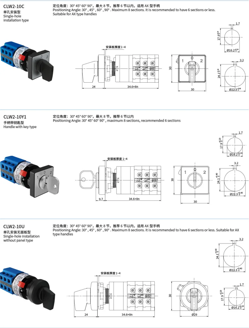
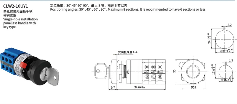
| CLW2-10C | AX handle; front plate | 30×30mm plate | 24mm | 34.6+8nmm, where n is the number of sections |
| CLW2-10Y1 | Key-operated; front plate | 9.7mm | ||
| CLW2-10U | AX handle; no front plate | Ø29mm base; 30mm illustrated overall front height | 24mm | |
| CLW2-10UY1 | Key-operated; no front plate | 9.7mm |
Mounting-panel thickness is 1–4mm. The drawings provide two keyed cutout alternatives: Ø16.2mm +0.2/0 with 17.9mm +0.2/0 overall keyed height and 1.7mm key width, or Ø22.3mm +0.4/0 with 24.1mm +0.4/0 keyed height and 3.2mm key width. Standard versions use a maximum of eight sections, with six or fewer recommended.
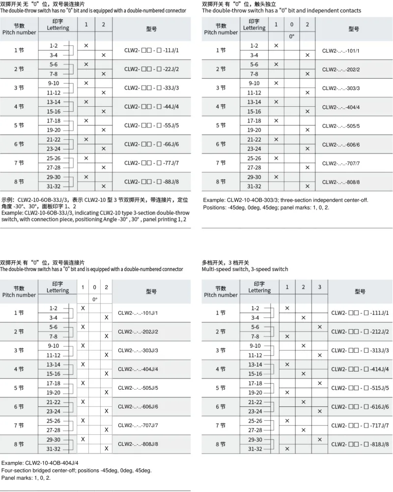
Each section contains two contact pairs. In the following schedules, a listed pair is closed; other pairs are open. Program suffixes identify the contact code and section count within the complete CLW2 ordering layout. Versions with even-number terminal bridges connect 2–4, 6–8, 10–12 and the corresponding even-terminal pair on each subsequent section.
| Sections | On/off program | Two-position, independent | Two-position, bridged | Center-off, independent | Center-off, bridged |
|---|---|---|---|---|---|
| 1 | 02/1 | 11/1 | 11J/1 | 101/1 | 101J/1 |
| 2 | 04/2 | 22/2 | 22J/2 | 202/2 | 202J/2 |
| 3 | 06/3 | 33/3 | 33J/3 | 303/3 | 303J/3 |
| 4 | 08/4 | 44/4 | 44J/4 | 404/4 | 404J/4 |
| 5 | 0A/5 | 55/5 | 55J/5 | 505/5 | 505J/5 |
| 6 | 0C/6 | 66/6 | 66J/6 | 606/6 | 606J/6 |
| 7 | 0E/7 | 77/7 | 77J/7 | 707/7 | 707J/7 |
| 8 | 0G/8 | 88/8 | 88J/8 | 808/8 | 808J/8 |
| Sections | Position 1 closed pairs, changeover | Position 2 closed pairs, changeover |
|---|---|---|
| 1 | 1–2 | 3–4 |
| 2 | 1–2, 5–6 | 3–4, 7–8 |
| 3 | 1–2, 5–6, 9–10 | 3–4, 7–8, 11–12 |
| 4 | 1–2, 5–6, 9–10, 13–14 | 3–4, 7–8, 11–12, 15–16 |
| 5 | 1–2, 5–6, 9–10, 13–14, 17–18 | 3–4, 7–8, 11–12, 15–16, 19–20 |
| 6 | 1–2, 5–6, 9–10, 13–14, 17–18, 21–22 | 3–4, 7–8, 11–12, 15–16, 19–20, 23–24 |
| 7 | 1–2, 5–6, 9–10, 13–14, 17–18, 21–22, 25–26 | 3–4, 7–8, 11–12, 15–16, 19–20, 23–24, 27–28 |
| 8 | 1–2, 5–6, 9–10, 13–14, 17–18, 21–22, 25–26, 29–30 | 3–4, 7–8, 11–12, 15–16, 19–20, 23–24, 27–28, 31–32 |
For the on/off programs, position 0 opens every pair; position 1 closes both pair groups in the selected section-count row. Two-position changeover uses positions 1 and 2 directly. Center-off changeover adds an all-open position 0 between positions 1 and 2. The bridged versions retain these contact-closure schedules and add the even-terminal links shown in the drawings.
| Complete example | Function | Angles | Panel labels |
|---|---|---|---|
| CLW2-10-4AB-06/3 | Three-section on/off | 0°, 45° | 0, 1 |
| CLW2-10-9OB-33/3 | Three-section independent changeover | −45°, 45° | 1, 2 |
| CLW2-10-6OB-33J/3 | Three-section bridged changeover | −30°, 30° | 1, 2 |
| CLW2-10-4OB-303/3 | Three-section independent center-off changeover | −45°, 0°, 45° | 1, 0, 2 |
| CLW2-10-4OB-404J/4 | Four-section bridged center-off changeover | −45°, 0°, 45° | 1, 0, 2 |

| Sections | Three-position program | Position 1 closed pairs | Position 2 closed pairs | Position 3 closed pairs |
|---|---|---|---|---|
| 1 | 111J/1 | 1–2 | 3–4 | None |
| 2 | 212J/2 | 1–2, 7–8 | 3–4 | 5–6 |
| 3 | 313J/3 | 1–2, 7–8 | 3–4, 9–10 | 5–6, 11–12 |
| 4 | 414J/4 | 1–2, 7–8, 13–14 | 3–4, 9–10, 15–16 | 5–6, 11–12 |
| 5 | 515J/5 | 1–2, 7–8, 13–14, 19–20 | 3–4, 9–10, 15–16 | 5–6, 11–12, 17–18 |
| 6 | 616J/6 | 1–2, 7–8, 13–14, 19–20 | 3–4, 9–10, 15–16, 21–22 | 5–6, 11–12, 17–18, 23–24 |
| 7 | 717J/7 | 1–2, 7–8, 13–14, 19–20, 25–26 | 3–4, 9–10, 15–16, 21–22, 27–28 | 5–6, 11–12, 17–18, 23–24 |
| 8 | 818J/8 | 1–2, 7–8, 13–14, 19–20, 25–26, 31–32 | 3–4, 9–10, 15–16, 21–22, 27–28 | 5–6, 11–12, 17–18, 23–24, 29–30 |
| Four-position program | Sections | Position 1 | Position 2 | Position 3 | Position 4 |
|---|---|---|---|---|---|
| 1111J/2 | 2 | 1–2 | 3–4 | 5–6 | 7–8 |
| 2222J/4 | 4 | 1–2, 9–10 | 3–4, 11–12 | 5–6, 13–14 | 7–8, 15–16 |
| 3333J/6 | 6 | 1–2, 9–10, 17–18 | 3–4, 11–12, 19–20 | 5–6, 13–14, 21–22 | 7–8, 15–16, 23–24 |
| 4444J/8 | 8 | 1–2, 9–10, 17–18, 25–26 | 3–4, 11–12, 19–20, 27–28 | 5–6, 13–14, 21–22, 29–30 | 7–8, 15–16, 23–24, 31–32 |
The five-position reference lists programs 1x5J/3, 2x5J/5, 3x5J/8 and 4x5J/10. Its illustrated contact schedule covers terminals 1–32 as follows; the 10-section reference is outside the eight-section standard mounting envelope.
| Five-position reference | Closed terminal pairs shown |
|---|---|
| Position 1 | 1–2, 17–18, 21–22 |
| Position 2 | 5–6, 11–12, 25–26, 31–32 |
| Position 3 | 7–8, 13–14, 27–28 |
| Position 4 | 9–10, 15–16, 29–30 |
| Position 5 | 3–4, 19–20, 23–24 |

A contact schedule defines each terminal pair's state at each operating position. The standard 424/3 example closes four pairs in positions 1 and 3 and two pairs in position 2. A custom suffix × identifies a schedule that requires its own contact diagram; it does not define that diagram by itself.
| Program | Position 1 closed pairs | Position 2 closed pairs | Position 3 closed pairs |
|---|---|---|---|
| 424/3 | 1–2, 3–4, 5–6, 7–8 | 9–10, 11–12 | 1–2, 3–4, 5–6, 7–8 |
| 424×/3, illustrated custom example | 1–2, 7–8, 11–12 | 5–6, 11–12 | 1–2, 3–4, 5–6, 7–8, 9–10 |
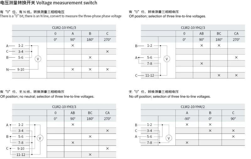
The schedules below state the closed terminal pairs at each panel position. All unlisted pairs are open. Keep the internal and external links in the corresponding wiring drawing when selecting phase-to-neutral or line-to-line measurements.
| Model | Measurement arrangement | Panel position, angle → closed terminal pairs |
|---|---|---|
| CLW2-10-YH1/3 | Three phase-to-neutral voltages; neutral connection and off position |
0, 0° → None
A, 90° → 1–2, 9–10 B, 180° → 5–6, 9–10 C, 270° → 3–4, 9–10 |
| CLW2-10-YH2/3 | Three line voltages; off position |
0, 0° → None
AB, 90° → 1–2, 7–8 BC, 180° → 1–2, 11–12 CA, 270° → 5–6, 11–12 |
| CLW2-10-YH3/3 | Three line voltages; no neutral; off position |
0, 0° → None
AB, 90° → 1–2, 7–8 BC, 180° → 5–6, 11–12 CA, 270° → 3–4, 9–10 |
| CLW2-10-YH4/2 | Three line-voltage selections; no off position; panel marks A/B/C |
A, −90° → 1–2, 7–8
B, 0° → 1–2, 3–4 C, 90° → 3–4, 5–6 |
| CLW2-10-YH12/2 | Three line voltages; no neutral; off position |
0, 0° → None
AB, 90° → 3–4, 5–6 BC, 180° → 5–6, 7–8 CA, 270° → 1–2, 7–8 |
| CLW2-10-YH13/2 | Three phase-to-neutral voltages; neutral connection; no off position; panel references A72/B100 |
A, 90° → 1–2, 7–8
B, 180° → 3–4, 7–8 C, 270° → 5–6, 7–8 |
| CLW2-10-YH22/3 | Three line voltages; no neutral; off position; panel references A75/B103 |
0, 0° → None
AB, 90° → 1–2, 7–8 BC, 180° → 5–6, 11–12 CA, 270° → 3–4, 9–10 |
| CLW2-10-YH5/4 | Three line and three phase-to-neutral voltages; neutral connection and off position |
CA, −135° → 5–6, 11–12
BC, −90° → 1–2, 15–16 AB, −45° → 3–4, 11–12 0, 0° → None AN, 45° → 7–8, 9–10 BN, 90° → 3–4, 13–14 CN, 135° → 1–2, 9–10 |
| CLW2-10-YH6/4 | Three line voltages from each of two supplies; off position |
Supply 1 CA, −135° → 3–4, 11–12
Supply 1 BC, −90° → 7–8, 15–16 Supply 1 AB, −45° → 3–4, 15–16 0, 0° → None Supply 2 AB, 45° → 1–2, 9–10 Supply 2 BC, 90° → 5–6, 13–14 Supply 2 CA, 135° → 1–2, 13–14 |
| CLW2-10-YH8/4 | Three line voltages and one phase-to-neutral voltage; neutral connection and off position |
CA, −135° → 5–6, 11–12
BC, −90° → 1–2, 15–16 AB, −45° → 3–4, 11–12 0, 0° → None AN, 45° → 7–8, 9–10 |

| Model | Current-transformer arrangement | Panel position, angle → closed terminal pairs |
|---|---|---|
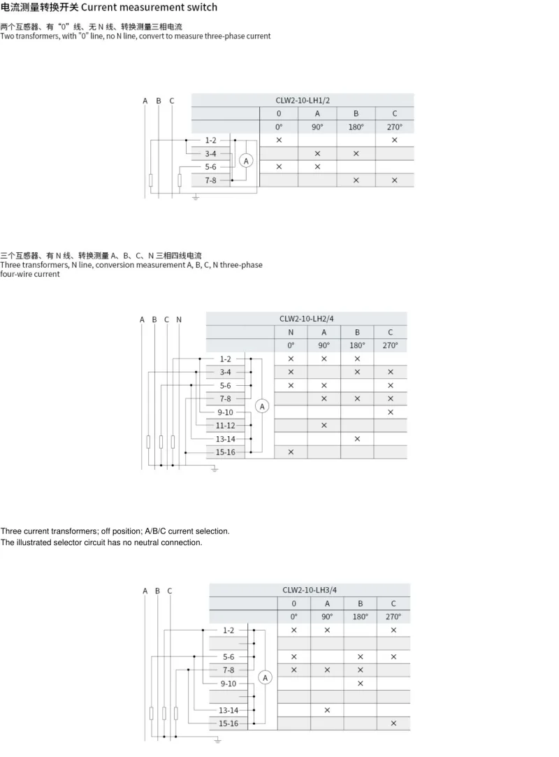
| CLW2-10-LH1/2 | Two current transformers; three-phase current selection; off position; no neutral |
0, 0° → 1–2, 5–6
A, 90° → 3–4, 5–6 B, 180° → 3–4, 7–8 C, 270° → 1–2, 7–8 |
| CLW2-10-LH2/4 | Three current transformers; three-phase/four-wire selection of N, A, B and C |
N, 0° → 1–2, 3–4, 5–6, 15–16
A, 90° → 1–2, 5–6, 7–8, 11–12 B, 180° → 1–2, 3–4, 7–8, 13–14 C, 270° → 3–4, 5–6, 7–8, 9–10 |
| CLW2-10-LH3/4 | Three current transformers; A/B/C current selection with off position |
0, 0° → 1–2, 5–6, 7–8
A, 90° → 1–2, 7–8, 13–14 B, 180° → 5–6, 7–8, 9–10 C, 270° → 1–2, 5–6, 15–16 |
The ammeter-selector off positions retain the contact closures shown above; they are not all-open schedules. Use the transformer and meter connections in the wiring drawings.
These programs distinguish six operating stages, including maintained states after closing or tripping. Repeated angles represent different operating histories; do not combine their contact states. Arrows in the wiring references identify the returning operating positions.
| Stage | Panel meaning | Handle direction | Angle |
|---|---|---|---|
| T | After trip | ← | −90° |
| PC | Pre-close | ↑ | 0° |
| C | Close | ↗ | 45°, returning position |
| CA | After close | ↑ | 0° |
| PT | Pre-trip | ← | −90° |
| TR | Trip | ↙ | −135°, returning position |
| Model | Closed terminal pairs by stage | Replacement reference |
|---|---|---|
| CLW2-10-ZJ/1a.4.6a.40.20/7 |
T: 2–4, 11–10, 15–14, 20–18
PC: 1–3, 9–10, 13–14, 17–18 C: 5–8, 9–12, 13–16, 17–19 CA: 1–3, 9–10, 13–16, 17–19 PT: 2–4, 11–10, 13–14, 17–18 TR: 6–7, 11–10, 15–14, 20–18 |
CLW2-10-Z-1a.4.6a.40.20/F8 |
| CLW2-10-Z/49.6781/8 |
T: 3–4, 15–16, 23–24, 31–32
PC: 1–2, 9–10, 21–22, 29–30 C: 5–6, 13–14, 25–26, 27–28 CA: 1–2, 9–10, 25–26, 27–28 PT: 3–4, 15–16, 21–22, 29–30 TR: 7–8, 15–16, 17–18, 23–24, 31–32 |
CLW2-10-Z-1a.4.6a.40.20/F8 |
| CLW2-10-Z/1a.4.20/4 |
T: 3–4, 13–14
PC: 1–2, 11–12 C: 5–6, 9–10 CA: 1–2, 9–10 PT: 3–4, 11–12 TR: 7–8, 13–14 |
CLW2-10-Z-1a.20/F8 |
| CLW2-10-ZJ/1a.4.6a.40.20/5 |
T: 3–4, 11–12, 13–14, 19–20
PC: 1–2, 9–10, 13–14 C: 5–6, 9–10, 15–16, 17–18 CA: 1–2, 9–10, 15–16, 17–18 PT: 3–4, 11–12, 13–14 TR: 7–8, 11–12, 13–14, 19–20 |
CLW2-10-Z-1a.4.6a.40.20/F8 |
| CLW2-10-ZJ/1a.4.6a.20/6 |
T: 2–4, 11–10, 16–14
PC: 1–3, 9–10, 13–14 C: 5–8, 9–12, 13–15 CA: 1–3, 9–10, 13–15 PT: 2–4, 11–10, 13–14 TR: 6–7, 11–10, 16–14 |
CLW2-10-Z-1a.4.6a.20/F8 |

| Model | Cabinet function | Stage positions and angles |
|---|---|---|
| CLW2-10-3OI-21-9/6 | Eight-stage main cabinet | Auto: −30°; 0–8: 0° to 240° in 30° steps |
| CLW2-10-3OG-21-7/5 | Six-stage main cabinet | Auto: −30°; 0–6: 0° to 180° in 30° steps |
| CLW2-10-3OK-21-AC/7 | Ten-stage main cabinet | Auto: −30°; 0–10: 0° to 300° in 30° steps |
| CLW2-10-3JF-0-8/4 | Eight-stage auxiliary cabinet | 0–8: −90° to 150° in 30° steps |
| CLW2-10-3JD-0-6/3 | Six-stage auxiliary cabinet | 0–6: −90° to 90° in 30° steps |
| CLW2-10-3JH-0-A/5 | Ten-stage auxiliary cabinet | 0–10: −90° to 210° in 30° steps |
The letter O in 3OI, 3OG and 3OK identifies the −30° start position; it is not a numeric zero. The main-cabinet Auto positions have no closed pairs in these schedules. In the following tables, “Not fitted” is outside that program's contact count, while “None” denotes a fitted pair that remains open.
| Terminal pair | Main cabinet, 8 stages: closed stages | Main cabinet, 6 stages: closed stages | Main cabinet, 10 stages: closed stages |
|---|---|---|---|
| 1–2 | 1–8 | 1–6 | 1–10 |
| 3–4 | 0 | 0 | 0 |
| 5–6 | 0 | 0 | 0 |
| 7–8 | 1–8 | 1–6 | 1–10 |
| 9–10 | 2–8 | 2–6 | 2–10 |
| 11–12 | 3–8 | 3–6 | 3–10 |
| 13–14 | 4–8 | 4–6 | 4–10 |
| 15–16 | 5–8 | 5–6 | 5–10 |
| 17–18 | 6–8 | 6 | 6–10 |
| 19–20 | 7–8 | None | 7–10 |
| 21–22 | 8 | Not fitted | 8–10 |
| 23–24 | None | Not fitted | 9–10 |
| 25–26 | Not fitted | Not fitted | 10 |
| 27–28 | Not fitted | Not fitted | 10 |
| Terminal pair | Auxiliary cabinet, 8 stages: closed stages | Auxiliary cabinet, 6 stages: closed stages | Auxiliary cabinet, 10 stages: closed stages |
|---|---|---|---|
| 1–2 | 1–8 | 1–6 | 1–10 |
| 3–4 | 2–8 | 2–6 | 2–10 |
| 5–6 | 3–8 | 3–6 | 3–10 |
| 7–8 | 4–8 | 4–6 | 4–10 |
| 9–10 | 5–8 | 5–6 | 5–10 |
| 11–12 | 6–8 | 6 | 6–10 |
| 13–14 | 7–8 | Not fitted | 7–10 |
| 15–16 | 8 | Not fitted | 8–10 |
| 17–18 | Not fitted | Not fitted | 9–10 |
| 19–20 | Not fitted | Not fitted | 10 |
All auxiliary-cabinet contacts are open at stage 0. The main ten-stage reference closes both 25–26 and 27–28 at stage 10; retain both contacts in the selected schedule.

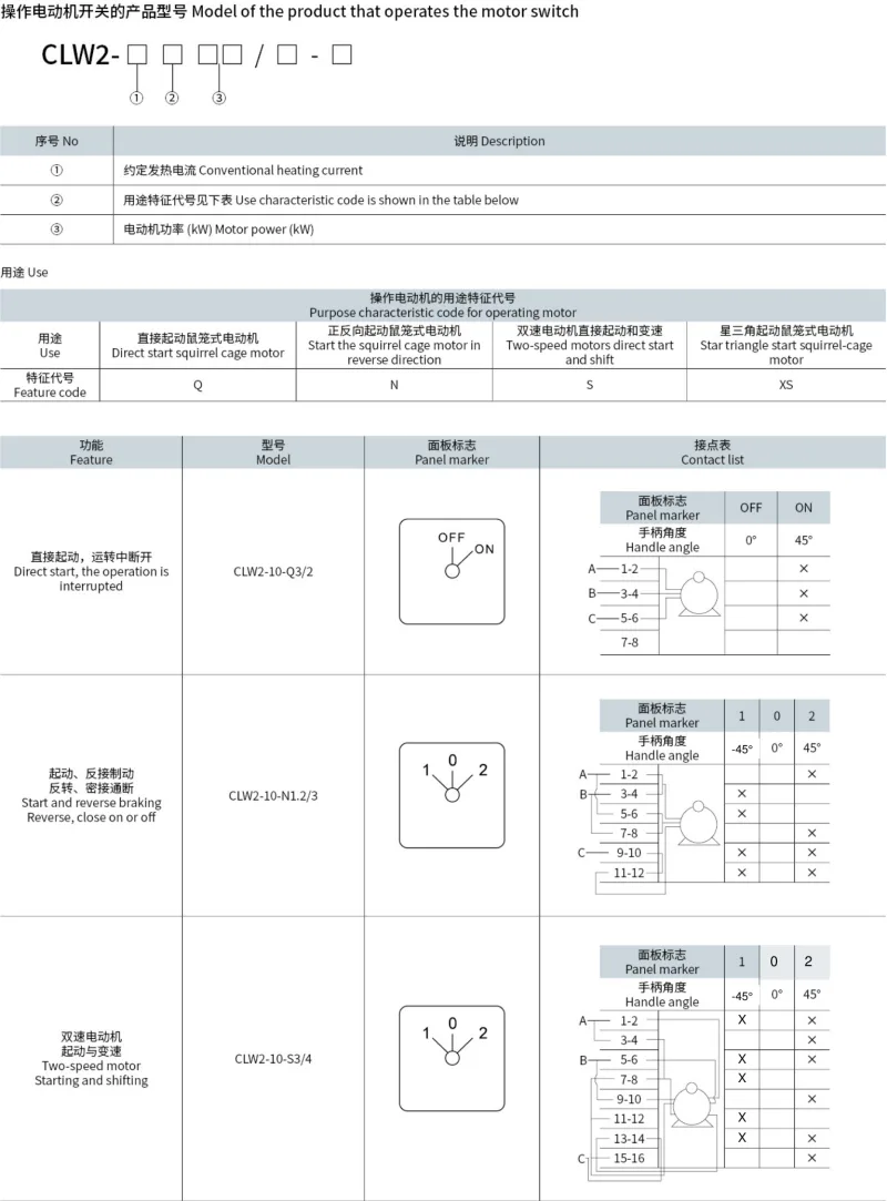
| Use code | Motor-control purpose |
|---|---|
| Q | Direct starting of a squirrel-cage motor |
| N | Forward/reverse starting |
| S | Two-speed motor starting and speed selection |
| XS | Star/delta starting |
The motor-application ordering fields identify thermal current, use code and motor power in kW, followed by the program's section and option fields. The application examples use 3 for 3kW and 1.2 for 1.2kW.
| Model | Application | Position, angle → closed terminal pairs |
|---|---|---|
| CLW2-10-Q3/2 | Direct starting; switching off during operation |
OFF, 0° → None
ON, 45° → 1–2, 3–4, 5–6 |
| CLW2-10-N1.2/3 | Starting, reversing and reverse-current braking |
1, −45° → 3–4, 5–6, 9–10, 11–12
0, 0° → None 2, 45° → 1–2, 7–8, 9–10, 11–12 |
| CLW2-10-S3/4 | Two-speed motor starting and speed selection |
1, −45° → 1–2, 5–6, 7–8, 11–12, 13–14
0, 0° → None 2, 45° → 1–2, 3–4, 5–6, 9–10, 13–14, 15–16 |
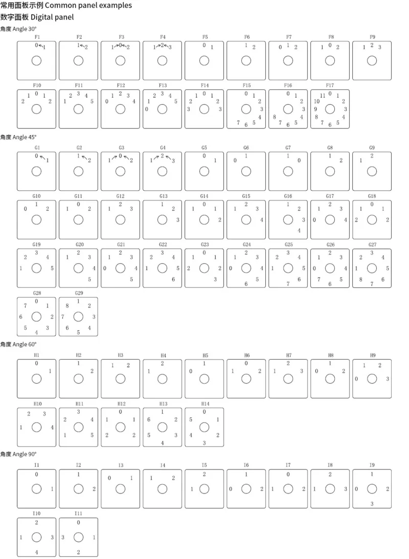
Panel print codes select the printed words, numbers and their physical layout. The following English equivalents describe the wording; use the matching illustrated plate for label locations and return arrows. Custom printing uses code P. Omitting a print code retains the standard printing for the selected contact schedule.
| Print-code group | Plate-layout angle | Content |
|---|---|---|
| A1–A22 | 30° | Worded operating and metering plates |
| B1–B59 | 45° | Worded operating, distribution and metering plates |
| C1–C18 | 60° | Worded operating plates |
| D1–D22 | 90° | Worded operating and metering plates |
| E1–E8 | 22.5° reference layouts | Multi-position numeric and Auto/Stop/Manual plates |
| F1–F17 | 30° | Numeric plates |
| G1–G29 | 45° | Numeric plates |
| H1–H14 | 60° | Numeric plates |
| I1–I11 | 90° | Numeric plates |
The plate library's 22.5° references describe print layouts; the standard CLW2-10 mechanisms above provide 30°, 45°, 60° and 90° operating steps.
| Print code | English wording / symbols |
|---|---|
| A1 / B1 | Raise / 0 / Lower |
| A2 / B2 | Start / 0 / Stop |
| A3 / B3 | Trip / Stop / Close |
| A4 / B4 | Trip / 0 / Close |
| A5 / B5 | Off / 0 / On |
| A6 / B6 | Remote / Stop / Local |
| A7 / B7 | Increase speed / 0 / Decrease speed |
| A8 / B8 | Trip / Disconnect / Close |
| A9 / B9 | Open / 0 / Close |
| A10 / B10 | Close / 0 / Trip |
| A11 / B11 | Trip / 0 / Close |
| A12 | OFF / ON |
| A13 | Trip / 0 / Close |
| A14 | Auto / 0 / Manual |
| A15 | Raise voltage / Stop / Lower voltage |
| A16 | On / Stop / Off |
| A17 | Close / 0 / Trip |
| A18 | Decrease speed / Stop / Increase speed |
| A19 | AB, BC, CA, 0, A, B, C |
| A20 | Auto / Stop / Manual / 2–6 |
| A21 | Auto / Stop / Manual / 2–8 |
| A22 | Auto / Stop / Manual / 2–10 |
| B12 | Remote / Local / Trip / Close, arranged as illustrated |
| B13 | Remote / After trip / After close / Trip / Close |
| B14 / B15 / B16 | Pre-close / After close / Close / Pre-trip / After trip / Trip; three illustrated layouts |
| B17 | Stop / Start |
| B18 | On / Off |
| B19 | Manual / Auto |
| B20 | Insert / Withdraw |
| B21 | Working / Test |
| B22 | Disconnect / Connect |
| B23 | Local / Remote |
| B24 | Switch cabinet / Operator station |
| B25 | Withdraw / Insert |
| B26 | Manual / Auto |
| B27 | Remote / Local |
| B28 | Disconnect / Connect |
| B29 | Auto / Standby |
| B30 | Stop / Start |
| B31 | Field / Remote |
| B32 | Remote / Field |
| B33 | Manual / Remote control |
| B34 | Withdraw / Insert |
| B35 | Interlock / Manual |
| B36 | On / Off |
| B37 | Test / Run |
| B38 | Disconnect / Remote |
| B39 | 1 / 2 / 3 / OFF |
| B40 | Trip / 0 / Close |
| B41 | Auto / Stop / Manual |
| B42 | Trip / 0 / Close |
| B43 | Run / Stop / Test |
| B44 | Increase excitation / Stop / Decrease excitation |
| B45 | Manual / Disconnect / Auto |
| B46 | Decrease speed / Disconnect / Increase speed |
| B47 | Raise voltage / Stop / Lower voltage |
| B48 | Local / Stop / Remote |
| B49 | Manual / Stop / Auto |
| B50 | Parallel / 0 / Separate |
| B51 | Local / 0 / Remote |
| B52 | Local / Disconnect / Remote |
| B53 | Decrease / 0 / Increase |
| B54 | Low voltage / High voltage |
| B55 | Local / 0 / Remote control |
| B56 | Parallel / 0 / Separate |
| B57 | Working / Stop / Standby |
| B58 | 0 and two sets of UAB / UBC / UCA |
| B59 | 0, UAB / UBC / UCA and UA / UB / UC |
| C1 | Manual / Auto |
| C2 | Remote / Local |
| C3 | Local / Remote |
| C4 | Trip / Close |
| C5 | Off / On |
| C6 | Auto / Manual |
| C7 | Manual / Auto |
| C8 | Parallel / Release |
| C9 | Auto / Manual |
| C10 | Local / Remote |
| C11 | Remote / Local |
| C12 | Trip / Disconnect / Close |
| C13 | Decrease speed / Disconnect / Increase speed |
| C14 | Manual / Stop / Auto |
| C15 | Auto / Stop / Manual |
| C16 | Local / Release / Remote |
| C17 | Manual / Reset / Auto |
| C18 | Remote / Local |
| D1 | Manual / Auto |
| D2 | Local / Remote |
| D3 | Auto / Manual |
| D4 | Remote / Local |
| D5 | Trip / Close |
| D6 | On / Off |
| D7 | Field / Remote |
| D8 | Close / Trip |
| D9 | Release / Parallel |
| D10 | Test / Run |
| D11 | Disabled / Enabled |
| D12 | Trip / Close |
| D13 | Field / Remote |
| D14 | Withdraw / Insert |
| D15 | Interlock / Release |
| D16 | IA / IB / IC |
| D17 | UAB / UBC / UCA |
| D18 | UA / UB / UC |
| D19 | 0, UA / UB / UC |
| D20 | 0, UAB / UBC / UCA |
| D21 | 0, IA / IB / IC |
| D22 | 0, IAB / IBC / ICA |
| E1 | 0–12 |
| E2 | 0–13 |
| E3 | Auto / Stop / Manual / 2–11 |
| E4 | Auto / Stop / Manual / 2–12 |
| E5 | Auto / Stop / Manual / 2–13 |
| E6 | Auto / Stop / Manual / 2–14 |
| E7 | 0–15 |
| E8 | 0–16 |


| Numeric print code | Printed numbers / return marks |
|---|---|
| F1 / G1 | 0 ← 1 |
| F2 / G2 | 1 ← 2 |
| F3 / G3 | 1 → 0 ← 2 |
| F4 / G4 | 1 → 2 ← 3 |
| F5 | 0, 1 |
| F6 | 1, 2 |
| F7 | 0, 1, 2 |
| F8 | 1, 0, 2 |
| F9 | 1, 2, 3 |
| F10 | 2, 1, 0, 1, 2 |
| F11 | 1–5 |
| F12 | 0–4 |
| F13 | 0–5 |
| F14 | 3, 2, 1, 0, 1, 2, 3 |
| F15 | 0–7 |
| F16 | 0–8 |
| F17 | 0–11 |
| G5 / G6 | 0, 1; distinct illustrated layouts |
| G7 | 1, 0 |
| G8 / G9 | 1, 2; distinct illustrated layouts |
| G10 | 0, 1, 2 |
| G11 | 1, 0, 2 |
| G12 / G13 | 1, 2, 3; distinct illustrated layouts |
| G14 | 1, 0, 1, 2 |
| G15 / G16 | 1–4; distinct illustrated layouts |
| G17 | 0–4 |
| G18 | 2, 1, 0, 1, 2 |
| G19 / G20 | 1–5; distinct illustrated layouts |
| G21 | 0–5 |
| G22 | 1–6 |
| G23 | 2, 1, 0, 1, 2, 3 |
| G24 | 0–6 |
| G25 | 1–7 |
| G26 | 0–7 |
| G27 | 1–8 |
| G28 | 0–7, circular layout |
| G29 | 1–8, circular layout |
| H1 | 0, 1 |
| H2 / H3 / H4 | 1, 2; distinct illustrated layouts |
| H5 | 0, 1 |
| H6 | 1, 0, 2 |
| H7 | 1, 2, 3 |
| H8 | 0, 1, 2 |
| H9 | 0–3 |
| H10 | 1–4 |
| H11 | 1–5 |
| H12 | 2, 1, 0, 1, 2 |
| H13 | 1–6 |
| H14 | 0–5 |
| I1 | 0, 1 |
| I2 | 1, 2 |
| I3 | 0, 1 |
| I4 | 1, 2 |
| I5 | 1, 2 |
| I6 | 0, 1, 2 |
| I7 | 1, 0, 2 |
| I8 | 1, 2, 3 |
| I9 | 0–3 |
| I10 | 1–4 |
| I11 | 0–3 |
Define a custom switch by thermal current, mechanical function, handle code, panel wording, handle directions and the closed/open state of every required contact pair at each position. The contact worksheet provides pairs 1–2 through 47–48 as a general specification grid; its blank twelve-section layout does not establish the maximum section count of a standard CLW2-10 mechanism.

The standard minimum applicable load is 24VDC, 10mA. Smaller signals require a suitable small-load contact configuration. Contacts already used on general loads should not subsequently be reused for smaller-capacity signals, because contact-surface changes can reduce reliability at low current. Use a suitable CR suppression or contact-protection circuit where bounce, noise or pulse currents affect the application.

The complete selection file includes the contact diagrams, panel-print library, custom worksheet and industrial-use precautions. Regional specifications may differ.
