


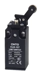


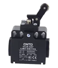


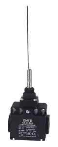


| Part Number: | CLS | - | 1 | 21M |
|---|---|---|---|---|
| Explanation: |
Series CLS - Vertical limit switch series |
Body 1 - Rectangular enclosure |
Actuator 01 - Flat plunger |
CLS vertical limit switches use a plastic enclosure, a double-spring contact mechanism and snap-action 1NO+1NC contacts. Select the rectangular CLS-1 body for a narrow mounting footprint or the square CLS-3 body for its wider mounting arrangement. Both formats offer IP65 protection and plunger, cantilever, rotary lever and flexible spring actuators.
| Rectangular body model | Square body model | Actuator and working dimensions |
|---|---|---|
| CLS-101 | CLS-301 | Flat metal plunger, Ø8mm |
| CLS-102 | CLS-302 | Vertical roller plunger; stainless roller Ø12.7×3.8mm |
| CLS-103 | CLS-303 | Transverse roller plunger; stainless roller Ø12.7×3.8mm |
| CLS-111 | CLS-311 | Left horizontal cantilever roller; stainless roller Ø12.7×3.8mm |
| CLS-112 | CLS-312 | Right horizontal cantilever roller; stainless roller Ø12.7×3.8mm |
| CLS-127 | CLS-327 | Vertical cantilever roller; stainless roller Ø12.7×3.8mm |
| CLS-121 | CLS-321 | Bent short lever with resin roller; Ø18×6.5mm, radius 27.2mm |
| CLS-121M | CLS-321M | Bent short lever with metal roller; Ø18×6.5mm, radius 27.2mm |
| CLS-131 | CLS-331 | Adjustable lever with resin roller; Ø18×6.5mm, radius 29.5–72.5mm |
| CLS-131M | CLS-331M | Adjustable lever with metal roller; Ø18×6.5mm, radius 29.5–72.5mm |
| CLS-191 | CLS-391 | Adjustable lever with large rubber roller; Ø50×8mm, radius 40–85mm |
| CLS-161 | CLS-361 | Flexible whisker; Ø1.5mm tip, Ø6.5mm nominal spring |
| CLS-171 | CLS-371 | Plastic rod on coil spring; Ø3.2mm rod, Ø6.5mm spring |
| CLS-181 | CLS-381 | Coil spring actuator; Ø6.5mm spring |
| Body format | Body width | Body depth | Horizontal mounting dimensions |
|---|---|---|---|
| CLS-1 rectangular | 31mm maximum | 30mm | 20±0.1mm / 22±0.1mm |
| CLS-3 square | 59.5mm | 29mm | 20–22mm inner slots; 40–42mm outer slots |
The two bodies share contact and rating information but have different mounting envelopes. Use the model-specific drawings in the attachment for head height, offsets and mounting-slot geometry.
The code comprises CLS, a hyphen, body code and one complete actuator code. For example, CLS-121M identifies the rectangular body with a bent short metal-roller lever. The M character belongs to the complete actuator code, such as 21M or 31M.
| Segment | Code | Meaning |
|---|---|---|
| Series | CLS | Vertical limit switch family |
| Body | 1 | Rectangular enclosure |
| 3 | Square enclosure | |
| Actuator | 01 | Flat plunger |
| 02 | Vertical roller plunger | |
| 03 | Transverse roller plunger | |
| 11 | Left horizontal cantilever roller | |
| 12 | Right horizontal cantilever roller | |
| 27 | Vertical cantilever roller | |
| 21 | Bent short lever, plastic roller | |
| 21M | Bent short lever, metal roller | |
| 22 | Straight short lever, plastic roller | |
| 22M | Straight short lever, metal roller | |
| 31 | Adjustable lever, plastic roller | |
| 31M | Adjustable lever, metal roller | |
| 61 | Flexible whisker | |
| 71 | Plastic rod coil spring | |
| 81 | Coil spring | |
| 91 | Adjustable lever, large roller |
Codes 22 and 22M are additional head options; the model comparison above lists the 28 configurations covered on this page.
| Parameter | Value |
|---|---|
| Contact arrangement | 1NO+1NC, snap action; NO terminals 13–14, NC terminals 11–12 |
| Operating speed | 5mm/s–0.5m/s |
| Electrical switching frequency | 30 operations/min |
| Initial contact resistance | 25mΩ maximum |
| Insulation resistance | 100MΩ minimum at 500VDC |
| Minimum load | 24VDC, 10mA |
| Rated insulation voltage Ui | 380V |
| Rated impulse withstand voltage Uimp | 2.5kV |
| Conventional thermal current Ith | 10A |
| Enclosure protection | IP65 |
| Vibration | 10–55Hz; 1.5mm double amplitude |
| Shock, mechanical durability | 1,000m/s² |
| Shock, malfunction resistance | 300m/s² |
| Operating temperature | -20°C to +70°C, no icing |
| Ambient humidity | Below 95%RH |
| Dielectric test location | Test voltage | Frequency and duration |
|---|---|---|
| Between open terminals of the same polarity | 1,000VAC | 50/60Hz for 1 minute |
| Between current-carrying and non-current-carrying metal | 1,500VAC | |
| Between each terminal and ground |
| Electrical endurance | Test condition | Applicability |
|---|---|---|
| More than 500,000 operations | 250VAC, 6A resistive | Shared CLS series rating |
| More than 300,000 operations | 240VAC, 3A resistive | Additional rating stated for the listed models other than CLS-112 and CLS-302 |
Endurance figures are lower limits under the stated test loads, not interchangeable predictions of service life.
| Voltage | Non-inductive loads | Inductive loads | ||||||
|---|---|---|---|---|---|---|---|---|
| Resistive | Lamp | Inductive | Motor | |||||
| NC | NO | NC | NO | NC | NO | NC | NO | |
| 125VAC | 6A | 1.5A | 0.7A | 3A | 2A | 1A | ||
| 250VAC | 6A | 1A | 0.5A | 3A | 1.5A | 0.8A | ||
| 12VDC | 6A | 3A | 4A | 3A | ||||
| 24VDC | 6A | 3A | 4A | 3A | ||||
| 125VDC | 0.4A | 0.2A | — | — | — | |||
| 50VDC | 0.4A | 0.2A | — | — | — | |||
Values are steady-state current ratings. Inductive-load conditions use an AC power factor of 0.4 or a DC time constant below 7ms. Lamp loads assume inrush up to ten times running current; motor loads assume six times running current. A dash indicates no stated rating.
| Contact | Maximum inrush current |
|---|---|
| NC | 24A |
| NO | 12A |
| Utilization category | Rated current | Rated voltage |
|---|---|---|
| AC-15 | 6A | 250V |
| DC-13 | 0.3A | 220V |
| Declared conformity reference | Standard |
|---|---|
| CCC | GB/T14048.5 |
| CE | EN60947-5-1 |
Obtain documentation for the selected configuration where a project requires certification evidence.
OF is maximum operating force; RF is minimum release force. PT and MD are maximum pretravel and movement differential. OT and TT are minimum overtravel and total travel. Trigger position TP has a ±10% tolerance. Linear and angular quantities are identified separately.
| Models | OF | RF | PT | TP ±10% | MD | OT | TT | Lever rotation angle |
|---|---|---|---|---|---|---|---|---|
| CLS-101, CLS-102, CLS-103 | 7N | 2N | 1.8mm | 2mm | 1.2mm | 4mm | 5.8mm | — |
| CLS-111, CLS-112, CLS-127 | 3mm | |||||||
| CLS-121, CLS-121M, CLS-131, CLS-131M, CLS-191 | 5N | 1N | 20° | 22.5° | 10° | 75° | 95° | 22.5° |
| CLS-161, CLS-171, CLS-181 | 1N | 0.4N | 30mm | 22.5° | 14° | 20mm | 50mm | — |
The same maximum/minimum definitions apply. Select using the exact model row: operating and release forces differ among these configurations.
| Models | OF | RF | PT | TP ±10% | MD | OT | TT |
|---|---|---|---|---|---|---|---|
| CLS-301, CLS-302, CLS-303 | 7N | 2N | 1.8mm | 2mm | 1.2mm | 4mm | 5.8mm |
| CLS-311, CLS-312, CLS-327 | 3mm | ||||||
| CLS-321 | 7.5N | 1N | 20° | 22.5° | 10° | 75° | 95° |
| CLS-321M | 1.5N | 0.3N | 14° | ||||
| CLS-331 | 7.5N | 2N | 10° | ||||
| CLS-331M, CLS-391 | 1.5N | 0.3N | 14° | ||||
| CLS-361 | 7.5N | 1N | 30mm | 22.5° | 10° | 20mm | 50mm |
| CLS-371 | 1.5N | 0.3N | 14° | ||||
| CLS-381 | 7.5N | 2N |
Flexible-head PT, OT and TT are linear tip displacements, while their TP and MD values are angular. Do not apply the travel of a plunger to a flexible spring or rotary lever.
Choose the actuator to match the direction and geometry of the moving target, then check available travel and the required electrical load category. The IP65 enclosure protects against dust and water jets when correctly installed; it is not an immersion specification. Maintain secure mounting and appropriate cable sealing.
These industrial components require separate application assessment for personnel protection, high-reliability continuous systems, harsh outdoor or chemical conditions, explosive atmospheres, nuclear, aerospace and military service. Component ratings alone do not establish suitability for those uses.
