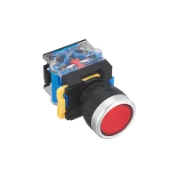
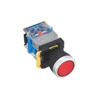
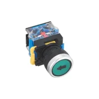

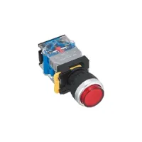
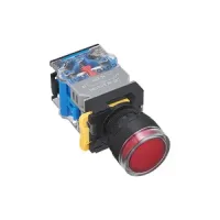
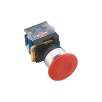
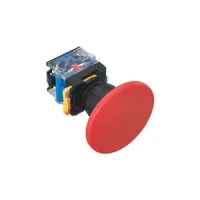
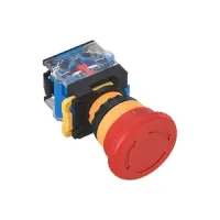
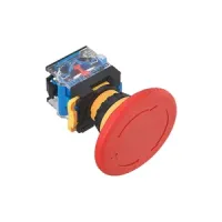
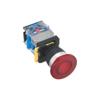
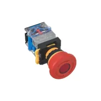


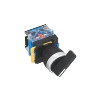

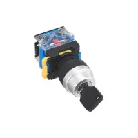
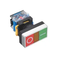

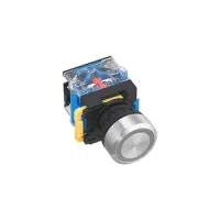
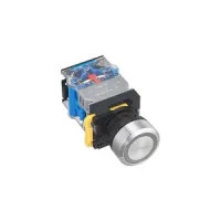
CNTD CLA38 is a modular control-operator range for 22mm panel holes. A pushbutton or selector head connects to an intermediate holder and quick-action contact blocks using a removable locking assembly. The range covers momentary and maintained buttons, illuminated operators, mushroom heads, emergency-stop operators, short and long selectors, key selectors, twin buttons and stainless steel heads.
The patterns below retain the listed 11 contact combination, meaning 1NO+1NC. Replace ○ with a color from the same row and △ with a suitable lamp-voltage code. A pattern containing △ is incomplete until its lamp voltage is selected. Color codes are W=white, B=black, G=green, R=red, Y=yellow and S=blue.
| Listed model pattern | Operator and action | Available color suffixes |
|---|---|---|
| CLA38-11PNL-○ | Flat, momentary | W, B, G, R, Y, S |
| CLA38-11PZL-○ | Flat, maintained | |
| CLA38-11PDL-○/△ | Illuminated flat, momentary | W, G, R, Y, S |
| CLA38-11PSL-○/△ | Illuminated flat, maintained | |
| CLA38-11PNL/F1-○ | Flat, momentary, direction legend | W, B, G, R, Y, S |
| CLA38-11PZL/F1-○ | Flat, maintained, direction legend | |
| CLA38-11GNL-○ | Raised, momentary | W, B, G, R, Y, S |
| CLA38-11GZL-○ | Raised, maintained | |
| CLA38-11GDL-○/△ | Illuminated raised, momentary | W, G, R, Y, S |
| CLA38-11GSL-○/△ | Illuminated raised, maintained | |
| CLA38-11PDT-○/△ | Transparent illuminated flat, momentary | W, G, R, Y, S |
| CLA38-11PST-○/△ | Transparent illuminated flat, maintained | |
| CLA38-11M40L-○ | 40mm mushroom, momentary | W, B, G, R, Y, S |
| CLA38-11MZ40L-○ | 40mm mushroom, maintained | |
| CLA38-11M60L-○ | 60mm mushroom, momentary | |
| CLA38-11MZ60L-○ | 60mm mushroom, maintained | |
| CLA38-11S40C-○ | 40mm emergency-stop operator | R, G, Y |
| CLA38-11S60C-○ | 60mm emergency-stop operator | |
| CLA38-11S40C/F6-○ | 40mm emergency-stop operator with STOP legend | |
| CLA38-11D40L-○/△ | Illuminated 40mm mushroom, momentary | W, G, R, Y, S |
| CLA38-11DZ40L-○/△ | Illuminated 40mm mushroom, maintained | |
| CLA38-11SD40C-○/△ | Illuminated 40mm emergency-stop operator | R, G, Y |
| CLA38-11PNWC-RG | Red/green twin flat buttons | RG=red and green |
| CLA38-11PDWC-RG/△-Y | Illuminated red/green twin flat buttons; listed yellow lamp suffix | Buttons R/G; lamp color choices W, G, R, Y |
| CLA38-11PNS-W | Stainless steel flat, momentary | W |
| CLA38-11PZS-W | Stainless steel flat, maintained | |
| CLA38-11PDS-○/△ | Illuminated stainless steel flat, momentary | W, G, R, Y, S |
| CLA38-11PSS-○/△ | Illuminated stainless steel flat, maintained |
Choose the head, contact arrangement, color and operating action for the intended control function. The mushroom and emergency-stop operator families are separate selections. An emergency-stop-shaped head alone does not define a complete machine safety function.
| Listed designation | Positions and action | Contacts | Key withdrawal |
|---|---|---|---|
| CLA38-11X21L-B CLA38-11XC21L-B | 2 positions, maintained; short / long handle | 1NO+1NC | Not applicable |
| CLA38-11X22L-B CLA38-11XC22L-B | 2 positions, spring return; short / long handle | ||
| CLA38-20X31L-B CLA38-20XC31L-B | 3 positions, maintained | 2NO | |
| CLA38-20X33L-B CLA38-20XC33L-B | 3 positions, spring return | ||
| CLA38-20X32L-B CLA38-20XC32L-B | 3 positions, left maintained / right spring return | ||
| CLA38-20X34L-B CLA38-20XC34L-B | 3 positions, left spring return / right maintained | ||
| CLA38-11XD21L-○/△ | Illuminated, 2 positions, maintained | 1NO+1NC | Not applicable |
| CLA38-11XD22L-○/△ | Illuminated, 2 positions, spring return | ||
| CLA38-20XD31L-○/△ | Illuminated, 3 positions, maintained | 2NO | |
| CLA38-20XD33L-○/△ | Illuminated, 3 positions, spring return | ||
| CLA38-11Y51L-B | 2 positions, maintained | 1NO+1NC | Both positions |
| CLA38-11Y53L-B | 2 positions, spring return | Left position | |
| CLA38-20Y61L-B | 3 positions, maintained | 2NO | All positions |
| CLA38-20Y62L-B | 3 positions, spring return | Right position |
The listed nonilluminated selector examples use B=black. The operator color legend also provides W/G/R/Y/S; illuminated XD patterns allow W/G/R/Y/S and require a lamp-voltage code. Three-position selectors must be installed with the TOP orientation mark aligned as shown in the installation drawing.
Contact bases can be combined up to four bases, with two groups of contact elements on each base. Silver-alloy contacts use a quick-action structure. The following code definitions describe the specified combinations; not every possible operator/contact combination is a listed product.
| Code | Contact combination | Block relationship |
|---|---|---|
| 01 | 1NC | Single NC group |
| 10 | 1NO | Single NO group |
| 02 | 2NC | Two NC groups |
| 20 | 2NO | Two NO groups |
| 11 | 1NO+1NC | Combined NO/NC |
| 22 | 2NO+2NC | 11+11 |
| 03 | 3NC | 02+01 |
| 30 | 3NO | 20+10 |
| 04 | 4NC | 02+02 |
| 40 | 4NO | 20+20 |
| 12 | 1NO+2NC | 11+01 |
| 21 | 2NO+1NC | 11+10 |
| 13 | 1NO+3NC | 11+02 |
| 31 | 3NO+1NC | 11+20 |
Separate block references are CLA-11=1NO+1NC, CLA-10=1NO and CLA-01=1NC. The block drawing gives 32.7mm overall axial reference, 24.5mm body reference, 36.6mm height and 29mm width. Terminal numbering uses the leading digit to distinguish contact pairs; terminal endings 1/2 identify NC and 3/4 identify NO.
C means a closed contact pair and O means an open pair. Read pairs from left to right, then the lower row where present, in the attachment's viewing orientation. These matrices describe contact states; use the operator's separate position code for maintained or spring-return behavior.
| Contact code | Two-position left | Two-position right | Three-position left | Three-position center | Three-position right |
|---|---|---|---|---|---|
| 11 | O,C | C,O | C,C | O,C | O,O |
| 20 | O,O | C,C | C,O | O,O | O,C |
| 02 | C,C | O,O | O,C | C,C | C,O |
| 22 | O,C / O,C | C,O / C,O | C,C / C,C | O,C / O,C | O,O / O,O |
| 31 | O,O / O,C | C,C / C,O | C,O / C,C | O,O / O,C | O,C / O,O |
| 13 | C,C / C,O | O,O / O,C | O,C / O,O | C,C / C,O | C,O / C,C |
| 40 | O,O / O,O | C,C / C,C | C,O / C,O | O,O / O,O | O,C / O,C |
| 04 | C,C / C,C | O,O / O,O | O,C / O,C | C,C / C,C | C,O / C,O |

| Field | Definition |
|---|---|
| Series | CLA38 |
| Contact combination | Use the 14 contact codes above |
| Operator | PN/PZ=momentary/maintained flat; PD/PS=illuminated flat; GN/GZ=momentary/maintained raised; GD/GS=illuminated raised; M40/M60=mushroom momentary; MZ40/MZ60=mushroom maintained; D40/D60=illuminated mushroom momentary; DZ40/DZ60=illuminated mushroom maintained; S40/S60=emergency-stop; SD40/SD60=illuminated emergency-stop; X=short selector; XC=long selector; XD=illuminated selector; Y=key selector; PNW=twin flat; PDW=illuminated twin flat. The 60mm illuminated options are general code choices without selection rows above. |
| Selector position | 21=2-position maintained; 22=2-position spring return; 31=3-position maintained; 32=left maintained/right spring return; 33=3-position spring return; 34=left spring return/right maintained |
| Head/function | L=aluminum head; C=plastic head; T=transparent head; S=stainless steel head. Blank=conventional; F=IP65 option; K=interference-resistant option. |
| Legend | F1=down arrow; F2=O; F3=I; F4=II; F5=START; F6=STOP; F7=up/down arrow. Legends can be combined with special requirements where available. |
| Color | W=white; B=black; G=green; R=red; Y=yellow; S=blue. Use the restricted color choices in each selection row; illuminated operators exclude B. |
| Lamp voltage | Choose the code below; lamp voltage is separate from the switch-contact load rating |
| Key-position option | Operating action | Removable-key positions |
|---|---|---|
| 51 | 2-position maintained | Both |
| 52 | Left | |
| 53 | 2-position spring return | Left |
| 61 | 3-position maintained | All |
| 62 | 3-position spring return | Right |
| 63 | 3-position maintained | Center |
| 64 | Left and right | |
| 65 | 3-position spring return | Center |
| 66 | 3 positions, left maintained / right spring return | Center |
| 67 | 3-position maintained | Left |
| 68 | Right |
The extended key-position choices define the code scheme. Full selection rows are provided above for 51, 53, 61 and 62. Confirm availability of other combinations before specifying an order.
| Code | Rated lamp voltage | Code | Rated lamp voltage |
|---|---|---|---|
| T | 6VAC/DC | J | 12VAC/DC |
| B | 24VAC/DC | C | 36VAC/DC |
| E | 48VAC/DC | FD | 110VAC/DC |
| MD | 220VAC/DC | QD | 380VAC/DC |
| F | 110VAC | M | 220VAC |
| Q | 380VAC | — | — |
Bidirectional LEDs are specified with a service life of at least 40000h. Lamp-holder circuit diagrams identify X1/X2 connections and separate AC/DC and AC-only circuits. Match the selected holder and lamp rating to the supply.
Rated insulation voltage Ui is 600V and thermal current Ith is 10A. The operating current depends on voltage and load category. The 10A thermal rating does not apply to every switched load.
| Supply | Load category | 24V | 120V | 240V | 380V |
|---|---|---|---|---|---|
| AC, 50/60Hz | AC-12 resistive | 10A | 10A | 6A | 2A |
| AC-15 inductive | 10A | 6A | 3A | 1.9A | |
| DC | DC-12 resistive | 8A | 2.2A | 1.1A | — |
| DC-13 inductive | 4A | 1.1A | 0.55A | — |
Dimensions below are millimeters. H is the front-head height reference in the drawing, and D is the illustrated rear assembly reference. All listed assemblies show a 42×29.5mm contact-base envelope and a 24.5mm lower-block reference. The drawings, rather than a sum of isolated references, define the complete assembly.
| Operator groups | Front width / diameter | H | D |
|---|---|---|---|
| PNL, PZL, PNL/F1, PZL/F1 | Ø29.6 | 12.3 | 50.7 |
| PDL, PSL | 66.7 | ||
| GNL, GZL | 17.3 | 50.7 | |
| GDL, GSL | 66.7 | ||
| PDT, PST | Ø29.6 | 14.3 | 66.7 |
| M40L, MZ40L | Ø40 | 22.5 | 50.7 |
| M60L, MZ60L | Ø60 | 24 | 50.7 |
| S40C, S40C/F6 | Ø40 | 24 | 50.7 |
| S60C | Ø60 | 24 | 50.7 |
| D40L, DZ40L | Ø40 | 23 | 66.7 |
| SD40C | Ø40 | 24 | 66.7 |
| X short selector | Ø29.6 | 25.6 | 50.7 |
| XC long selector | 38.5 handle width; Ø29.6 bezel | 23.6 | 50.7 |
| XD illuminated selector | Ø29.6 | 25.3 | 66.7 |
| Y key selector | Ø29.6 | 37.5 including illustrated key | 50.7 |
| PNWC twin | 54.2×29.8 | 17.5 | 50.7 |
| PDWC illuminated twin | 66.7 | ||
| PNS, PZS stainless steel | 29.3 | 10 | 50.7 |
| PDS, PSS illuminated stainless steel | 66.7 |
| Item | Specification |
|---|---|
| Contact resistance | ≤50mΩ |
| Insulation resistance | ≥100MΩ |
| Minimum standard load | 24VDC, 10mA |
| Power-frequency withstand | 1890VAC, 50Hz, 60s |
| Vibration | 10–55Hz, 0.75mm amplitude |
| Resistance to unintended operation under shock | Emergency-stop operators:150m/s²; pushbutton operators:100m/s² |
| Protection | IP65 at the working face for the stated configuration. The broader range includes IP40 and optional IP65 variants; specify the required seal option. |
| Electrical endurance | ≥200000operations at 3A/220V resistive load |
| Ambient conditions | −25 to +55°C without icing; 45–85%RH |
| Wiring capacity | Maximum2×1.5mm² or 1×2.5mm²; minimum2×0.75mm²; maximum blade6.3×0.8mm |
| Material / construction | Flame-retardant engineering materials; silver-alloy contacts; removable head/holder/contact assembly |
| Referenced standards | GB/T14048.5 and EN60947-5-1; A600 and N600 utilization references. Supporting certificates are not included. |
Press the holder latch to separate the head, holder and contact assembly. Install through a 22mm panel hole and use the appropriate installation wrench. Observe the TOP mark for three-position selectors; other illustrated operators do not require directional mounting.
Standard contacts are intended for loads of at least 24VDC/10mA. Do not move contacts previously used for general loads into a lower-load circuit. Below this level, contact films may prevent reliable switching; obtain a suitable low-load version. The attachment retains the low-load area graph, including its 5mW and 800mW boundaries and current/voltage reference lines. Use suitable suppression for switching noise and pulse loads to preserve contact life.
Regional specifications can vary. Applications involving personnel safety, unusually high reliability, nuclear/gas/power systems, harsh outdoor or contaminated conditions, fire or explosion hazards, strong acids or alkalis, and military or aerospace equipment require a product specifically designed and confirmed for that purpose.
