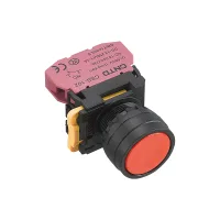


CNTD CLA37 modular operators fit 22mm panel holes and combine a removable head, intermediate holder and quick-action contact elements. Flat and raised pushbuttons, mushroom heads, emergency-stop operators, short and long selectors, key selectors, twin buttons and stainless steel heads support panel control layouts. Match the complete color/contact designation to the required circuit.
Color codes are W=white, B=black, G=green, R=red, Y=yellow and S=blue. In the tables below, ○ may be replaced only with a color listed in the same cell. △ is the selected lamp-voltage code. Red and nonred selections use different contact codes in the listed single-contact combinations:01=1NC and 10=1NO.
| Operator | Listed 1NO patterns and colors | Listed red 1NC designation |
|---|---|---|
| Flat, momentary | CLA37-10PNC-○:W/B/G/Y/S | CLA37-01PNC-R |
| Flat, maintained | CLA37-10PZC-○:W/B/G/Y/S | CLA37-01PZC-R |
| Transparent illuminated flat, momentary | CLA37-10PDT-○/△:W/G/Y/S | CLA37-01PDT-R/△ |
| Transparent illuminated flat, maintained | CLA37-10PST-○/△:W/G/Y/S | CLA37-01PST-R/△ |
| Flat with direction legend, momentary | CLA37-10PNC/F1-○:W/B/G/Y/S | CLA37-01PNC/F1-R |
| Flat with direction legend, maintained | CLA37-10PZC/F1-○:W/B/G/Y/S | CLA37-01PZC/F1-R |
| Raised, momentary | CLA37-10GNC-○:W/B/G/Y/S | CLA37-01GNC-R |
| Raised, maintained | CLA37-10GZC-○:W/B/G/Y/S | CLA37-01GZC-R |
| Illuminated raised, momentary | CLA37-10GDC-○/△:W/G/Y/S | CLA37-01GDC-R/△ |
| Illuminated raised, maintained | CLA37-10GSC-○/△:W/G/Y/S | CLA37-01GSC-R/△ |
| 40mm mushroom, momentary | CLA37-10M40C-○:W/B/G/Y/S | CLA37-01M40C-R |
| 40mm mushroom, maintained | CLA37-10MZ40C-○:W/B/G/Y/S | CLA37-01MZ40C-R |
| 60mm mushroom, momentary | CLA37-10M60C-○:W/B/G/Y/S | CLA37-01M60C-R |
| 60mm mushroom, maintained | CLA37-10MZ60C-○:W/B/G/Y/S | CLA37-01MZ60C-R |
| Illuminated 40mm mushroom, momentary | CLA37-10D40C-○/△:W/G/Y/S | CLA37-01D40C-R/△ |
| Illuminated 40mm mushroom, maintained | CLA37-10DZ40C-○/△:W/G/Y/S | CLA37-01DZ40C-R/△ |
| 60mm emergency-stop operator | CLA37-10S60C-○:G/Y | CLA37-01S60C-R |
| Illuminated 40mm emergency-stop operator | CLA37-10SD40C-○/△:G/Y | CLA37-01SD40C-R/△ |
| 40mm emergency-stop operator with STOP legend | CLA37-10S40C/F6-○:G/Y | CLA37-01S40C/F6-R |
| 40mm rotary-release emergency-stop operator | CLA37-10S40C-○:G/Y | CLA37-01S40C-R |
| Stainless steel flat, momentary | CLA37-10PNS-W | No red selection listed |
| Stainless steel flat, maintained | CLA37-10PZS-W | |
| Illuminated stainless steel flat, momentary | CLA37-10PDS-○/△:W/G/Y/S | CLA37-01PDS-R/△ |
| Illuminated stainless steel flat, maintained | CLA37-10PSS-○/△:W/G/Y/S | CLA37-01PSS-R/△ |
PN/PZ and GN/GZ distinguish momentary from maintained action. The mushroom and emergency-stop operator families are separate selections. Verify the complete machine control function and required contact action when specifying an emergency-stop operator.
| Twin operator | Listed designation | Contacts | Colors |
|---|---|---|---|
| Nonilluminated twin flat | CLA37-11PNWC-RG | 1NO+1NC | Red/green buttons |
| Illuminated twin flat | CLA37-11PDWC-RG/△-Y | Red/green buttons; listed yellow lamp suffix. Lamp-color choices:W/G/R/Y. |
| Designation | Operating action | Contacts | Key withdrawal |
|---|---|---|---|
| CLA37-10X21C-B CLA37-10XC21C-B | 2-position maintained, short / long handle | 1NO | Not applicable |
| CLA37-10X22C-B CLA37-10XC22C-B | 2-position spring return, short / long handle | ||
| CLA37-20X31C-B CLA37-20XC31C-B | 3-position maintained | 1NO+1NO | |
| CLA37-20X33C-B CLA37-20XC33C-B | 3-position spring return | ||
| CLA37-20X32C-B CLA37-20XC32C-B | Left maintained / right spring return | ||
| CLA37-20X34C-B CLA37-20XC34C-B | Left spring return / right maintained | ||
| CLA37-10Y21C-B | 2-position maintained | 1NO | Both positions |
| CLA37-10Y22C-B | 2-position spring return | Left | |
| CLA37-20Y31C-B | 3-position maintained | 1NO+1NO | All positions |
| CLA37-20Y33C-B | 3-position spring return | Right | |
| CLA37-10XD21L-○/△ | Illuminated, 2-position maintained | 1NO | Not applicable |
| CLA37-10XD22L-○/△ | Illuminated, 2-position spring return | ||
| CLA37-20XD31L-○/△ | Illuminated, 3-position maintained | 1NO+1NO | |
| CLA37-20XD33L-○/△ | Illuminated, 3-position spring return |
Listed nonilluminated selector/key examples are black. The operator color legend also identifies W/G/R/Y/S. Illuminated XD examples retain their L suffix and offer G/R/Y colors; add the chosen lamp-voltage code.
Up to four contact bases can be combined, each accommodating two groups of contact elements. CBS-101 is a 1NO block, CBS-102 is 1NC, CBS-201 is 2NO and CBS-202 is 2NC. Contact codes distinguish combined individual blocks from L-coded multi-contact arrangements.
| Code | Specified structure | Total contacts |
|---|---|---|
| 01 | 1NC | 1NC |
| 02 | 01+01 | 2NC |
| 03 | 02L+01 | 3NC |
| 10 | 1NO | 1NO |
| 11 | 1NO+1NC | 1NO+1NC |
| 12 | 11L+01 | 1NO+2NC |
| 20 | 10+10 | 2NO |
| 21 | 11L+10 | 2NO+1NC |
| 30 | 20L+10 | 3NO |
| 02L | 2NC arrangement | 2NC |
| 20L | 2NO arrangement | 2NO |
| 11L | 1NO+1NC arrangement | 1NO+1NC |
| 12L | 02L+02L | 4NC |
| 21L | 20L+20L | 4NO |
| 22L | 11L+11L | 2NO+2NC |
These extended definitions describe contact construction, rather than confirming every possible complete operator model. Terminal endings 1/2 denote NC and 3/4 denote NO; the preceding digit distinguishes contact pairs.
C=closed contact pair and O=open contact pair. Read pairs left to right in the illustrated viewing direction. The contact matrix is separate from the selector's maintained or spring-return action.
| Contact code | Two-position left | Two-position right | Three-position left | Three-position center | Three-position right |
|---|---|---|---|---|---|
| 10 | O | C | No matrix listed | ||
| 01 | C | O | No matrix listed | ||
| 20 | O,O | C,C | C,O | O,O | O,C |
| 02 | C,C | O,O | O,C | C,C | C,O |
| 11 | O,C | C,O | C,C | O,C | O,O |

| Field | Choices and meaning |
|---|---|
| Series | CLA37 |
| Contact | Use the contact-code table and the exact listed operator combination |
| Operation | PN/PZ=momentary/maintained flat; PD/PS=illuminated flat; GN/GZ=momentary/maintained raised; GD/GS=illuminated raised; M40/M60=mushroom momentary; MZ40/MZ60=mushroom maintained; D40/D60=illuminated mushroom momentary; DZ40/DZ60=illuminated mushroom maintained; S40/S60=emergency-stop; SD40/SD60=illuminated emergency-stop; X=short selector; XC=long selector; XD=illuminated selector; Y=key selector; PNW=twin flat; PDW=illuminated twin flat. PD/PS and 60mm illuminated options are general guide choices without full selection rows above. |
| Selector position | 21=2-position maintained; 22=2-position spring return; 31=3-position maintained; 32=left maintained/right spring return; 33=3-position spring return; 34=left spring return/right maintained |
| Function/head | C=plastic head; T=transparent head; S=stainless steel head. The listed illuminated XD models retain their specific L suffix. |
| Custom legend | Add / for a custom legend:F1=down arrow; F2=O; F3=I; F4=II; F5=START; F6=STOP; F7=up/down arrow |
| Color | W=white; B=black; G=green; R=red; Y=yellow; S=blue. Availability depends on the selected operator; illuminated selections exclude black. |
| Lamp | Add the required voltage code after / for an illuminated operator |
An extended key-code scheme also defines 51=two-position maintained with withdrawal at both positions; 52=two-position maintained, withdrawal left; 53=two-position spring return, withdrawal left; 61=three-position maintained, withdrawal at all positions; 62=three-position spring return, withdrawal right; 63=three-position maintained, withdrawal center; 64=three-position maintained, withdrawal left/right; 65=three-position spring return, withdrawal center; 66=left maintained/right spring return, withdrawal center; 67=three-position maintained, withdrawal left; and 68=three-position maintained, withdrawal right. The actual listed Y models above use 21/22/31/33; confirm availability before specifying another key-code combination.
| Code | Voltage | Code | Voltage |
|---|---|---|---|
| T | 6VAC/DC | J | 12VAC/DC |
| B | 24VAC/DC | C | 36VAC/DC |
| E | 48VAC/DC | FD | 110VAC/DC |
| MD | 220VAC/DC | QD | 380VAC/DC |
| F | 110VAC, guide option | M | 220VAC, guide option |
| Q | 380VAC, guide option | — | — |
The bidirectional LED specification lists eight AC/DC voltages, red/green/yellow/blue/white colors and at least 40000h service life. Its lamp-holder schematic uses X1/X2 terminals. The extended guide also includes AC-only F/M/Q codes; select a compatible lamp holder. Lamp supply voltage is independent of the switch-contact rating.
Ui=600V; Ith=10A; contact material is silver alloy. Use the load-category rating at the actual operating voltage, rather than applying the thermal-current figure to every circuit.
| Supply | Category | 24V | 120V | 240V | 380V |
|---|---|---|---|---|---|
| AC, 50/60Hz | AC-12 resistive | 10A | 10A | 6A | 2A |
| AC-15 inductive | 10A | 6A | 3A | 1.9A | |
| DC | DC-12 resistive | 8A | 2.2A | 1.1A | — |
| DC-13 inductive | 4A | 1.1A | 0.55A | — |
All dimensions are millimeters. H is the front-height reference and D is the rear-assembly reference shown in the drawings. Most illustrated CLA37 assemblies use a 43×29.5mm contact-base envelope and 22.6mm lower-block reference. The illuminated twin assembly has its own larger rear construction.
| Operator group | Front dimensions | H | D | Rear reference |
|---|---|---|---|---|
| PNC, PZC, PNC/F1, PZC/F1, PDT, PST | Ø29.6 | 12.3 | 48.6 | 43×29.5 envelope;22.6 lower block |
| GNC, GZC, GDC, GSC | Ø29.6 | 17.3 | ||
| M40C, MZ40C | Ø40 | 22.5 | ||
| M60C, MZ60C | Ø60 | 24 | ||
| D40C, DZ40C | Ø40 | 23.6 | ||
| S60C | Ø60 | 24 | ||
| SD40C | Ø40 | 24 | ||
| S40C/F6 STOP legend | Ø40 | 24 | ||
| S40C rotary release | Ø40.4 | 26.8 | ||
| X short selector | Ø29.6 | 25.5 | ||
| XC long selector | 38.5 handle width;Ø29.6 bezel | 24 | ||
| PNS, PZS, PDS, PSS stainless steel | Ø29.6 | 10 | ||
| Y key selector | Ø29.6 | 37.5 including illustrated key | ||
| XD illuminated selector | Ø29.6 | 25.5 | ||
| PNWC twin | 54.2×29.8 | 17.5 | 48.6 | 43×29.5 envelope;22.6 lower block |
| PDWC illuminated twin | 54.2×29.8 | 17.5 | 66.7 | 42×29.5 envelope;24.5 lower block |
| Item | Specification |
|---|---|
| Contact resistance | ≤50mΩ |
| Insulation resistance | ≥100MΩ |
| Minimum standard load | 24VDC,10mA |
| Dielectric withstand | 1890VAC,50Hz,60s |
| Vibration | 10–55Hz,0.75mm amplitude |
| Shock resistance against unintended operation | Emergency-stop operators:150m/s²;pushbutton operators:100m/s² |
| Working-face protection | IP65 for the specified configuration. The wider range includes IP40 and optional IP65 versions; specify the required sealing arrangement. |
| Electrical endurance | ≥200000operations at 3A/220V resistive load |
| Ambient conditions | −25 to +55°C without icing;45–85%RH |
| Wire / terminal capacity | Maximum2×1.5mm² or1×2.5mm²;minimum2×0.75mm²;maximum blade6.3×0.8mm |
| Referenced standards | GB/T14048.5;EN60947-5-1;A600/N600 category references. Supporting certificates are not included. |
Use the latch to separate the head, holder and contact elements. Mount through a 22mm hole and use an appropriate installation wrench. Three-position selectors require alignment with the TOP mark; other illustrated operators do not require directional mounting.
Standard contacts require at least 24VDC/10mA. Contacts previously used for general loads should not be reused for smaller loads. Below the stated minimum, surface films can prevent reliable switching; obtain a suitable low-load version. The attachment includes the low-load graph with its 5mW/800mW boundaries. Provide suitable suppression for switching noise and pulse currents to maintain contact life.
Regional specifications can vary. Personnel-safety functions, exceptionally high-reliability nuclear/gas/power systems, harsh outdoor or contaminated environments, fire/explosion hazards, strong acids or alkalis, and military/aerospace applications require a product specifically designed and confirmed for the purpose.
