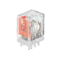


CK miniature general-purpose relays combine plug-in mounting with mechanical indication and indicator-equipped configurations. CKE-2CS, CKE-4CS and CKL-2CS have separate contact ratings; AC and DC coil codes select the supply independently of the switched circuit. Match the contact form, load type, coil supply and socket before selecting a relay.
| Model | Changeover contacts | Resistive load | Motor load | Listed resistive switching power | Initial contact resistance | Between-pole initial dielectric strength |
|---|---|---|---|---|---|---|
| CKE-2CS | 2C | 5A at 250VAC or 30VDC | 1/6HP at 240VAC | 1750VA; 210W | 50mΩ | 1000VAC for 1 minute; leakage current 1mA |
| CKE-4CS | 4C | 3A at 250VAC or 30VDC | 750VA; 90W | ≤100mΩ | ||
| CKL-2CS | 2C | 10A at 250VAC or 30VDC | 1/3HP at 240VAC | 2500VA; 300W | 1500VAC for 1 minute; leakage current 1mA |
Contact current, motor load and listed switching power are separate selection limits. The switching-power figure does not increase the stated contact-current rating.
The following characteristics apply to the three rated models above. Voltage percentages refer to the rated coil voltage, Un.
| Parameter | Value and condition |
|---|---|
| Contact material | Silver alloy |
| Electrical endurance | ≥100,000 operations; 1s ON and 1s OFF, 1800 operations/h |
| Mechanical endurance | ≥10,000,000 operations; 300 operations/min, 18,000 operations/h |
| Pick-up voltage at 23°C | DC ≤75%Un; AC ≤80%Un |
| Drop-out voltage at 23°C | DC ≥10%Un; AC ≥30%Un |
| Maximum coil voltage at 23°C | 110%Un |
| Insulation resistance | ≥500MΩ at 500VDC |
| DC coil power | Approximately 0.9W |
| AC coil power | Approximately 1.2VA |
| Operate time at rated voltage | ≤20ms |
| Release time at rated voltage | |
| Initial dielectric strength between open contacts | 1000VAC for 1 minute; leakage current 1mA |
| Initial dielectric strength between contacts and coil | 1500VAC for 1 minute; leakage current 1mA |
| Ambient temperature | -25–55°C |
| Ambient humidity | 35–85%RH |
| Air pressure | 86–106kPa |
| Shock resistance | 10G; sinusoidal half-wave pulse, 11ms |
| Vibration resistance | 10–55Hz; 1.0mm double amplitude |
| Mounting | Plug-in |
| Voltage code | Coil supply | Nominal voltage | Coil resistance | Standard code |
|---|---|---|---|---|
| 009 | DC | 9VDC | 90Ω | No standard mark |
| 012 | 12VDC | 180Ω | Yes | |
| 024 | 24VDC | 640Ω | ||
| 036 | 36VDC | 1500Ω | No standard mark | |
| 048 | 48VDC | 2600Ω | Yes | |
| 110 | 110VDC | 13,000Ω | No standard mark | |
| 220 | 220VDC | 42,000Ω | ||
| 712 | AC | 12VAC | 40Ω | No standard mark |
| 724 | 24VAC | 180Ω | Yes | |
| 736 | 36VAC | 370Ω | No standard mark | |
| 748 | 48VAC | 640Ω | Yes | |
| 710 | 110VAC | 4430Ω | No standard mark | |
| 730 | 230VAC | 16,500Ω | Yes | |
| 780 | 380VAC | 42,000Ω | No standard mark |
The standard-code column corresponds to the starred coil selections. Other listed codes remain available selections; the star is not part of the ordering code.
| Field | Code | Meaning |
|---|---|---|
| Resistive current family | E | 3A or 5A, according to contact configuration |
| L | 10A | |
| Contact form | 2C | Two changeover groups |
| 4C | Four changeover groups | |
| Mounting | S | Plug-in |
| P | Soldered | |
| Coil voltage | See coil-code table | Select the full AC or DC voltage code |
| Option | 13 | Function unspecified |
The illustrated 3CS and LT models below have their own outline references. Separate electrical ratings for those variants and the meaning of LT are unspecified here.

Dimensions are in mm. The body envelope is 27max×21max×36max; pin projection is stated separately.
| Model | Body envelope | Pin projection | Pin width | Pin thickness |
|---|---|---|---|---|
| CKE-2CS | 27max×21max×36max | 6.0 | 2.5 | 0.5 |
| CKE-3CS | ||||
| CKE-4CS | ||||
| CKL-2CS | 6.8 | 4.8 | ||
| CKE-2CS-LT | 6.0 | 2.5 | ||
| CKE-3CS-LT | ||||
| CKE-4CS-LT | ||||
| CKL-2CS-LT | 6.8 | 4.8 |


| Socket model | Load current | Load voltage | Dielectric withstand | Retaining accessory |
|---|---|---|---|---|
| CYF08A-E | 7A | 300V | 2500VAC for 1s | CRS-E |
| CYF08A-K | CRS-K | |||
| CYF14A-E | 5A | CRS-E | ||
| CYF14A-K | CRS-K | |||
| CTF08A-E | 10A | CRS-E | ||
| CTF08A-K | CRS-K |

These relays are intended for industrial control. Applications requiring exceptional reliability or safety, including gas and power systems, railways, elevators, medical and security equipment, require a specially designed product and written application approval. The same requirement applies to harsh outdoor, chemically contaminated, electromagnetic, vibration or impact environments; fire or explosion hazards involving flammable gases, strong acids or alkalis; military uses and large engineering projects.
