


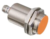

CNTD CJY-E/M economy cylindrical inductive sensors combine contactless metal detection with a straight male M12 four-pin A-coded connector. M12, M18 and M30 sensing housings cover 2–15mm nominal distances, with flush and nonflush heads, red operating indicators and IP65 protection. Select the sensing housing independently from the M12 electrical connector size.
These transistor models operate at 10–30VDC. DNA/DNB mean NPN NO/NC; DPA/DPB mean PNP NO/NC. DNC and DPC identify NO+NC outputs. A model with two outputs requires its matching connection arrangement; the single-output pinout below does not define both outputs.
| Head and installation | NPN models | PNP models |
|---|---|---|
| M12, 2mm, flush | CJY12E-02DNA/M CJY12E-02DNB/M CJY12E-02DNC/M | CJY12E-02DPA/M CJY12E-02DPB/M CJY12E-02DPC/M |
| M12, 4mm, nonflush | CJY12E-04DNA/M CJY12E-04DNB/M CJY12E-04DNC/M | CJY12E-04DPA/M CJY12E-04DPB/M CJY12E-04DPC/M |
| M18, 5mm, flush | CJY18E-05DNA/M CJY18E-05DNB/M CJY18E-05DNC/M | CJY18E-05DPA/M CJY18E-05DPB/M CJY18E-05DPC/M |
| M18, 8mm, nonflush | CJY18E-08DNA/M CJY18E-08DNB/M CJY18E-08DNC/M | CJY18E-08DPA/M CJY18E-08DPB/M CJY18E-08DPC/M |
| M30, 10mm, flush | CJY30E-10DNA/M CJY30E-10DNB/M CJY30E-10DNC/M | CJY30E-10DPA/M CJY30E-10DPB/M CJY30E-10DPC/M |
| M30, 15mm, nonflush | CJY30E-15DNA/M CJY30E-15DNB/M CJY30E-15DNC/M | CJY30E-15DPA/M CJY30E-15DPB/M CJY30E-15DPC/M |
| Head / nominal distance | DC two-wire NO / NC | AC two-wire NO / NC |
|---|---|---|
| M12 / 2mm | CJY12E-02DLA/M CJY12E-02DLB/M | No model listed |
| M12 / 4mm | CJY12E-04DLA/M CJY12E-04DLB/M | CJY12E-04DKA/M CJY12E-04DKB/M |
| M18 / 5mm | CJY18E-05DLA/M CJY18E-05DLB/M | CJY18E-05DKA/M CJY18E-05DKB/M |
| M18 / 8mm | CJY18E-08DLA/M CJY18E-08DLB/M | CJY18E-08DKA/M CJY18E-08DKB/M |
| M30 / 10mm | CJY30E-10DLA/M CJY30E-10DLB/M | CJY30E-10DKA/M CJY30E-10DKB/M |
| M30 / 15mm | CJY30E-15DLA/M CJY30E-15DLB/M | CJY30E-15DKA/M CJY30E-15DKB/M |
DKA/M and DKB/M in this AC table are 90–250VAC models. DLA/M and DLB/M are 10–30VDC models. Match the complete designation to its circuit rating rather than applying the general voltage-letter guide to an AC table entry.
| Model group | Nominal distance | Setting distance | Standard iron target | NPN / PNP response | DC two-wire response |
|---|---|---|---|---|---|
| CJY12E-02/M | 2mm | 0–1.4mm | 12×12×1mm | 1000Hz | 1000Hz |
| CJY12E-04/M | 4mm | 0–2.8mm | 500Hz | 500Hz | |
| CJY18E-05/M | 5mm | 0–3.5mm | 18×18×1mm | 500Hz | 500Hz |
| CJY18E-08/M | 8mm | 0–5.6mm | 25×25×1mm | 350Hz | 350Hz |
| CJY30E-10/M | 10mm | 0–7mm | 30×30×1mm | 400Hz standard; 350Hz premium version | 350Hz |
| CJY30E-15/M | 15mm | 0–10.5mm | 45×45×1mm | 200Hz | 200Hz |
AC two-wire models respond at 20Hz. These are average response frequencies measured using the specified standard target, twice the target width as the interval between successive targets, and a sensing gap equal to half the nominal detection distance. The setting range defines the operating gap used for selection.
| Item | NPN / PNP | DC two-wire | AC two-wire |
|---|---|---|---|
| Operating supply | 10–30VDC | 90–250VAC | |
| Output current | 200mA maximum | ||
| Leakage current | ≤10mA | ≤0.6mA | ≤10mA |
| Residual voltage | ≤1V | ≤3.5V | ≤10V |
| Protection circuit | Surge, reverse-polarity and overcurrent protection | Surge protection | |
| Hysteresis | ≤10% of nominal sensing distance | ||
| Temperature influence | Within ±10% of the sensing distance at 20°C over −25 to +70°C | ||
The attachment shows separate standard and IEC DC two-wire pin arrangements. Select the matching sensor and cordset configuration; connector appearance alone does not establish the pinout. Pin numbering and orientation are shown in the attached connector-face drawings.
| Circuit | Connections | Unused or linked pins | Load arrangement |
|---|---|---|---|
| DC two-wire, standard, NO or NC | Pin 4: brown lead / positive side; pin 3: blue / 0V side | Pins 1 and 2 unused | Sensor in series with the load; the load may be connected in either lead |
| DC two-wire, IEC, NO | Pin 1: brown / positive side; pin 4: blue / 0V side | Pins 2 and 3 unused | |
| DC two-wire, IEC, NC | Pin 1: brown / positive side; pin 2: blue / 0V side | Pins 3 and 4 unused | |
| NPN, single output | Pin 1: brown / +V; pin 3: blue / 0V; pin 4: black / output | Pin 2 not assigned in the illustrated single-output circuit | Between +V and output pin 4 |
| PNP, single output | Pin 1: brown / +V; pin 3: blue / 0V; pin 4: black / output | Pin 2 not assigned in the illustrated single-output circuit | Between output pin 4 and 0V |
| AC two-wire, NO or NC | Brown and blue leads form the two sides of the switching circuit | Pins 1 and 4 internally linked; pins 2 and 3 internally linked | Sensor and load in series on 90–250VAC; load may be in either lead |
With a conventional DC three-wire connector cable on the standard DC two-wire configuration, the black cable conductor on pin 4 serves the positive side and blue on pin 3 serves 0V; brown on pin 1 is unused. Tighten the connector to 0.39–0.49N·m. The installation instructions call for securing the connection and cable with tape at locations subject to vibration.

| Position | Element | Choices and meaning |
|---|---|---|
| 1 | CJ | Inductive sensing |
| 2 | Y | Cylindrical metal housing |
| 3 | Size | 12=M12, 18=M18, 30=M30 in the model tables. The general guide also identifies 08=M8, without a corresponding full connector model here. |
| 4 | E | Economy type |
| 5 | Thread length | Blank=standard; L=long thread. Illustrated dimensions apply to standard bodies. |
| 6 | Distance | 02=2mm, 04=4mm, 05=5mm, 08=8mm, 10=10mm, 15=15mm |
| 7 | Supply letter | General guide: A=90–250VAC, D=10–30VDC, E=20–60VDC, J=5–10VDC. For the listed DKA/M and DKB/M AC variants, use their specific 90–250VAC rating. |
| 8 | Output | N=NPN; P=PNP; K=AC two-wire; L=DC two-wire |
| 9 | Output state | A=NO; B=NC; C=NO+NC |
| 10 | M | Straight male M12 four-pin A-coded connector, following the slash in the complete model |
| Housing | Sensing thread | Overall axial reference | Thread-length reference | Front projection | Nut reference |
|---|---|---|---|---|---|
| CJY12E-02/M, flush | M12×1 | 65mm | 50mm | Flush | Ø21mm, 17mm across flats, 4mm thick |
| CJY12E-04/M, nonflush | 60mm | 45mm | 7mm | ||
| CJY18E-05/M, flush | M18×1 | 65mm | 50mm | Flush | Ø29mm, 24mm across flats, 4mm thick |
| CJY18E-08/M, nonflush | 60mm | 45mm | 10mm | ||
| CJY30E-10/M, flush | M30×1.5 | 65mm | 50mm | Flush | Ø41mm, 36mm across flats, 5mm thick |
| CJY30E-15/M, nonflush | 60mm | 45mm | 11mm | Ø41mm, 35mm across flats as drawn, 5mm thick |
The rear electrical connector thread is M12×1 on all illustrated bodies. Dimensions follow the endpoints in the attached drawings, including the indicator location; no attached cordset length is included.
All values below are millimeters. A and B refer to the face-to-face and parallel spacing shown in the drawing. n is the head-exposure reference; Ød is the surrounding-metal opening diameter; ℓ and m follow the axial and surrounding-metal endpoints in the attached installation geometry.
| Model group | A | B | n | Ød | ℓ | m |
|---|---|---|---|---|---|---|
| CJY12E-02/M | 12 | 24 | 0 | 12 | 6 | 18 |
| CJY12E-04/M | 24 | 36 | 11 | 36 | 12 | 36 |
| CJY18E-05/M | 30 | 36 | 0 | 18 | 15 | 27 |
| CJY18E-08/M | 48 | 54 | 14 | 54 | 24 | 54 |
| CJY30E-10/M | 60 | 60 | 0 | 30 | 30 | 45 |
| CJY30E-15/M | 90 | 90 | 15 | 90 | 45 | 90 |
| Parameter | Rating |
|---|---|
| Protection / indicator | IP65; red operating LED |
| Operating / storage temperature | −25 to +70°C / −30 to +80°C, without icing |
| Humidity | 35–95%RH without condensation |
| Insulation resistance | ≥50MΩ at 500VDC |
| Dielectric strength | 1500VAC, 50/60Hz, 1min |
| Vibration | 1mm amplitude, 10–55Hz in a 1min sweep, 2h in each X/Y/Z direction |
| Shock | 500m/s², approximately 50G, three times in each X/Y/Z direction |
| Materials | Nickel-plated brass housing and nuts; nickel-plated iron washers; PBT sensing face |
| Standards referenced | CCC: GB/T14048.10; TÜV and CE: EN60947-5-2. Certification documents are not supplied in the guide. |
| Utilization-category references | DC-13: 10–30VDC, 200mA; AC-140: 24–250VAC, 200mA. Individual model operating ratings remain those in the electrical table. |
For industrial metal-position detection, match the target, operating gap, circuit and mounting clearance to the selected model. Regional specifications can differ. The manufacturer excludes personnel-safety functions, exceptionally high-reliability nuclear, gas and power systems, harsh outdoor or contaminated conditions, fire or explosion hazards, strong acids or alkalis, and military or aerospace applications unless specifically designed and confirmed for that use.
