

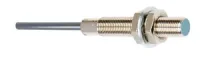


CNTD CJY cylindrical inductive proximity sensors detect metal targets without a mechanical actuator. Smooth miniature bodies and threaded M5–M30 versions support compact machine-position sensing, with 1–15mm nominal detection distances, red operating LEDs and IP67 protection. The model tables distinguish NPN/PNP transistor outputs from DC and AC two-wire circuits; their supply, residual voltage and leakage limits differ.
All models in this table operate at 10–30VDC. DNA is NPN NO, DNB is NPN NC, DPA is PNP NO and DPB is PNP NC. DNC and DPC provide complementary NO+NC outputs and use four conductors. NO+NC models are listed for M12, M18 and M30 only.
| Size / distance group | NPN models | PNP models |
|---|---|---|
| 04-01, miniature flush | CJY04-01DNA CJY04-01DNB | CJY04-01DPA CJY04-01DPB |
| 05-01, miniature flush | CJY05-01DNA CJY05-01DNB | CJY05-01DPA CJY05-01DPB |
| 06-01, miniature flush | CJY06-01DNA CJY06-01DNB | CJY06-01DPA CJY06-01DPB |
| 6.5-01, miniature flush | CJY6.5-01DNA CJY6.5-01DNB | CJY6.5-01DPA CJY6.5-01DPB |
| 08-01, flush | CJY08-01DNA CJY08-01DNB | CJY08-01DPA CJY08-01DPB |
| 08-02, nonflush | CJY08-02DNA CJY08-02DNB | CJY08-02DPA CJY08-02DPB |
| 12-02, flush | CJY12-02DNA CJY12-02DNB CJY12-02DNC | CJY12-02DPA CJY12-02DPB CJY12-02DPC |
| 12-04, nonflush | CJY12-04DNA CJY12-04DNB CJY12-04DNC | CJY12-04DPA CJY12-04DPB CJY12-04DPC |
| 18-05, flush | CJY18-05DNA CJY18-05DNB CJY18-05DNC | CJY18-05DPA CJY18-05DPB CJY18-05DPC |
| 18-08, nonflush | CJY18-08DNA CJY18-08DNB CJY18-08DNC | CJY18-08DPA CJY18-08DPB CJY18-08DPC |
| 30-10, flush | CJY30-10DNA CJY30-10DNB CJY30-10DNC | CJY30-10DPA CJY30-10DPB CJY30-10DPC |
| 30-15, nonflush | CJY30-15DNA CJY30-15DNB CJY30-15DNC | CJY30-15DPA CJY30-15DPB CJY30-15DPC |
| Size / nominal distance | DC two-wire NO / NC | AC two-wire NO / NC |
|---|---|---|
| M8 / 1mm | CJY08-01DLA CJY08-01DLB | No model listed |
| M8 / 2mm | CJY08-02DLA CJY08-02DLB | No model listed |
| M12 / 2mm | CJY12-02DLA CJY12-02DLB | No model listed |
| M12 / 4mm | CJY12-04DLA CJY12-04DLB | CJY12-04AKA CJY12-04AKB |
| M18 / 5mm | CJY18-05DLA CJY18-05DLB | CJY18-05AKA CJY18-05AKB |
| M18 / 8mm | CJY18-08DLA CJY18-08DLB | CJY18-08AKA CJY18-08AKB |
| M30 / 10mm | CJY30-10DLA CJY30-10DLB | CJY30-10AKA CJY30-10AKB |
| M30 / 15mm | CJY30-15DLA CJY30-15DLB | CJY30-15AKA CJY30-15AKB |
| Model group | Nominal distance | Setting distance | Standard iron target | DC response frequency |
|---|---|---|---|---|
| CJY04-01 | 1mm | 0–0.8mm | 6×6×1mm | 1500Hz |
| CJY05-01 | 7×7×1mm | |||
| CJY06-01 | 8×8×1mm | 1000Hz | ||
| CJY6.5-01 | 0–1.05mm | 8×8×1.5mm | ||
| CJY08-01 | 1mm | 0–0.8mm | 8×8×1mm | |
| CJY08-02 | 2mm | 0–1.4mm | ||
| CJY12-02 | 2mm | 0–1.4mm | 12×12×1mm | 1000Hz |
| CJY12-04 | 4mm | 0–2.8mm | 500Hz | |
| CJY18-05 | 5mm | 0–3.5mm | 18×18×1mm | 350Hz |
| CJY18-08 | 8mm | 0–5.6mm | 25×25×1mm | |
| CJY30-10 | 10mm | 0–7mm | 30×30×1mm | 350Hz standard; 400Hz premium NPN/PNP version |
| CJY30-15 | 15mm | 0–10.5mm | 45×45×1mm | 200Hz |
CJY6.5-01 is specified with a 1mm nominal sensing distance and its own 0–1.05mm setting-range entry; its model code is 01. AC two-wire models are rated at 20Hz. Response frequencies are average values measured with the specified standard iron target, an interval between successive targets equal to twice the target width, and a sensing gap of half the nominal distance.
| Parameter | DC NPN / PNP | DC two-wire | AC two-wire |
|---|---|---|---|
| Operating voltage | 10–30VDC | 90–250VAC | |
| Control output | 200mA maximum | ||
| Leakage current | ≤10mA | ≤0.6mA | ≤10mA |
| Residual voltage | ≤1V | ≤3.5V | ≤10V |
| Protection circuit | Surge, reverse-polarity and overcurrent protection | Surge protection | |
| Hysteresis | ≤10% of nominal sensing distance | ||
| Temperature influence | Within ±10% of the sensing distance at 20°C over −25 to +70°C | ||
| Size group | Cable diameter | Length | Conductors | Strands per conductor |
|---|---|---|---|---|
| 04, 05, 06, 6.5 | 2.8mm | 2m | 3P | 22 |
| 08 | 3P for a single NPN/PNP output; 2P for DC two-wire | |||
| 12 | 3.8mm | 3P for a single NPN/PNP output; 4P for NO+NC; 2P for DC or AC two-wire | 25 | |
| 18, 30 | 4.8mm | 30 |
The cable specification identifies AWG22, 0.1mm individual strand diameter and 1.25mm conductor insulation outside diameter. The strand count describes each conductor, rather than the number of external wires. Standard cable is gray PVC, with black oil-resistant PVC also described.

| Position | Element | Known choices |
|---|---|---|
| 1 | CJ | Inductive sensing |
| 2 | Housing | Y=cylindrical metal housing; YG=stainless-steel cylindrical housing; YS=plastic cylindrical housing. The listed CJY models use the Y designation; the alternative housing choices are not additional full models in these tables. |
| 3 | Size | 08=M8, 12=M12, 18=M18, 30=M30; miniature groups separately use 04, 05, 06 and 6.5. |
| 4 | Product type | Blank=standard type |
| 5 | Thread length | Blank=standard; L=long thread. The attached dimensions apply to the illustrated standard bodies. |
| 6 | Detection distance | 01=1mm, 02=2mm, 04=4mm, 05=5mm, 08=8mm, 10=10mm, 15=15mm |
| 7 | Supply | A=90–250VAC; D=10–30VDC. E=20–60VDC and J=5–10VDC are general guide choices, without full models in the selection tables. |
| 8 | Circuit | N=NPN; P=PNP; K=AC two-wire; L=DC two-wire |
| 9 | State | A=NO; B=NC; C=NO+NC, only for the groups that list combined outputs |
| 10 | Connection | Blank=free-ended cable; M=straight male M12 four-pin A-coded connector. M-type, DT, AMP and SM connector families have additional configuration placeholders without individual subcode definitions here. |
| 11 | Additional option placeholder | Shown in the layout; its option mapping is not specified in the accompanying guide. |
| 12 | Lead-length suffix | The layout shows L2 and the standard cable specification is 2m; additional suffix values are not defined in this guide. |
| Model group | Body / thread | Axial references | Front and mounting references |
|---|---|---|---|
| CJY04-01 | Smooth Ø4mm | 30mm body | Front reference Ø3.6mm; 2.8mm cable |
| CJY05-01 | M5×0.5 | 30mm overall body | Ø10mm nut, 8mm across flats; Ø4mm front reference; 2.6mm and 0.5mm axial details; 2.8mm cable |
| CJY06-01 | M6×0.75 | 35mm overall body | 10mm across flats; Ø5mm front reference; 2.7mm nut reference; 2.8mm cable |
| CJY6.5-01 | Smooth Ø6.4mm body / Ø6.7mm front reference | 55.2mm overall reference; 40mm body reference | 0.5mm and 1.7mm axial details; 2.8mm cable |
| Model group | Thread | Overall axial reference | Thread reference | Front projection | Nut dimensions |
|---|---|---|---|---|---|
| CJY08-01, flush | M8×1 | 52mm | 38mm | Flush | Ø15mm; 13mm across flats; 3mm thick |
| CJY08-02, nonflush | 47mm | 32mm | 5mm | ||
| CJY12-02, flush | M12×1 | 58mm | 38mm | Flush | Ø21mm; 17mm across flats; 4mm thick |
| CJY12-04, nonflush | 53mm | 32mm | 7mm | ||
| CJY18-05, flush | M18×1 | 63mm | 38mm | Flush | Ø29mm; 24mm across flats; 4mm thick |
| CJY18-08, nonflush | 58mm | 32mm | 10mm | ||
| CJY30-10, flush | M30×1.5 | 67mm | 38mm | Flush | Ø41mm; 36mm across flats; 5mm thick |
| CJY30-15, nonflush | 59mm | 32mm | 11mm |
Axial references follow the drawing endpoints and exclude the free cable. The attachment retains the complete dimension geometry, cable exit and operating-indicator locations.
All values are millimeters. A and B are the face-to-face and parallel installation dimensions in the attached drawing; n is the head-exposure reference; Ød is the surrounding-metal opening diameter; ℓ and m follow the illustrated axial and surrounding-metal measurement endpoints.
| Model group | A | B | n | Ød | ℓ | m |
|---|---|---|---|---|---|---|
| CJY08-01 | 9 | 16 | 0 | 8 | 4.5 | 12 |
| CJY08-02 | 12 | 24 | 8 | 24 | 6 | 24 |
| CJY12-02 | 12 | 24 | 0 | 12 | 6 | 18 |
| CJY12-04 | 24 | 36 | 11 | 36 | 12 | 36 |
| CJY18-05 | 30 | 36 | 0 | 18 | 15 | 27 |
| CJY18-08 | 48 | 54 | 14 | 54 | 24 | 54 |
| CJY30-10 | 60 | 60 | 0 | 30 | 30 | 45 |
| CJY30-15 | 90 | 90 | 15 | 90 | 45 | 90 |
For single NPN/PNP outputs, brown connects to +V, blue to 0V and black is the output. An NPN load connects between +V and black; a PNP load connects between black and 0V. DC and AC two-wire sensors connect in series with the load, which may be in either lead. Use 90–250VAC for the listed AC models. Single-output diagrams do not assign the extra conductor of NO+NC models.
| Illustrated input | Brown supply lead | Blue supply lead | Black output lead |
|---|---|---|---|
| PA10-U input 1 | 9 (+12V) | 10 (GND) | 11 (IN1) |
| PA10-U input 2 | 13 (+12V) | 14 (GND) | 15 (IN2) |
| FX4 counter | 10 (+12V) | 11 (0V) | 8 (CP1) |
These are external NPN three-wire connection examples. The FX4 counter drawing shows a separate 100–240VAC counter supply; that voltage is not applied to the sensor. The attachment includes the transistor and two-wire circuits, NO/NC timing diagrams and external input examples.
| Item | Specification |
|---|---|
| Protection / indication | IP67; red operating LED |
| Operating / storage temperature | −25 to +70°C / −30 to +80°C, without icing |
| Humidity | 35–95%RH, without condensation |
| Insulation resistance | ≥50MΩ at 500VDC |
| Dielectric strength | 1500VAC, 50/60Hz, 1min |
| Vibration | 1mm amplitude, 10–55Hz in a 1min sweep, 2h in each X/Y/Z direction |
| Shock | 500m/s², approximately 50G, three times in each X/Y/Z direction |
| Materials of listed Y models | Nickel-plated brass case and nuts; nickel-plated iron washers; PBT sensing face; gray PVC standard cable or black oil-resistant PVC cable |
| Standard references | CCC: GB/T14048.10; TÜV and CE: EN60947-5-2. The attachment does not include supporting certification documents. |
| Utilization-category references | DC-13: 10–30VDC, 200mA; AC-140: 24–250VAC, 200mA. Use the model-specific operating ratings for supply selection. |
Use within the rated target, gap, circuit and installation conditions for ordinary industrial metal-position sensing. Regional specifications can differ. The manufacturer excludes personnel-safety applications, exceptionally high-reliability nuclear, gas and power systems, severe outdoor or contaminated environments, fire or explosion hazards, strong acids or alkalis, and military or aerospace applications unless specifically designed and confirmed for that purpose.
