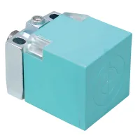


These flat inductive proximity sensors provide 20mm sensing in the CJF40Y and CJF40X formats, or 50mm sensing in the CJF80 format. Choose the housing and mounting arrangement, then match the setting distance, target size and electrical circuit. DC options include NPN, PNP and two-wire circuits; AC options use a two-wire circuit. PBT cases, red operation indicators and IP65 protection are specified.
| Model group | Sensing distance | Setting distance | Standard iron target | Average response frequency |
|---|---|---|---|---|
| CJF40Y-20 | 20mm | 0-15.5mm | 75×75×1mm | DC: 200Hz AC: 20Hz |
| CJF40X-20 | ||||
| CJF80-50 | 50mm | 0-40mm | 120×120×1mm |
The response-frequency values are averages measured with the standard sensing target, target spacing twice the standard target width and a sensing gap equal to half the nominal sensing distance.
| Housing group | DC NPN three-wire | DC PNP three-wire | DC two-wire | AC two-wire |
|---|---|---|---|---|
| 40Y | CJF40Y-20DNA CJF40Y-20DNB | CJF40Y-20DPA CJF40Y-20DPB | CJF40Y-20DLA CJF40Y-20DLB | CJF40Y-20AKA CJF40Y-20AKB |
| 40X | CJF40X-20DNA CJF40X-20DNB | CJF40X-20DPA CJF40X-20DPB | CJF40X-20DLA CJF40X-20DLB | CJF40X-20AKA CJF40X-20AKB |
| 80 | CJF80-50DNA CJF80-50DNB | CJF80-50DPA CJF80-50DPB | CJF80-50DLA CJF80-50DLB | CJF80-50AKA CJF80-50AKB |
The final A means NO and final B means NC. Supply code D is 10-30VDC; supply code A is 90-250VAC. N denotes NPN, P denotes PNP, L denotes DC two-wire and K denotes AC two-wire.
| Parameter | DC three-wire | DC two-wire | AC two-wire |
|---|---|---|---|
| Operating supply | 10-30VDC | 90-250VAC | |
| Response frequency | 200Hz under the stated target and gap conditions | 20Hz under the stated target and gap conditions | |
| Residual voltage | Maximum 1V | Maximum 3.5V | Maximum 10V |
| Leakage current | Maximum 10mA | ||
| Control output | Maximum 200mA | ||
| Hysteresis | Maximum 10% of sensing distance | ||
| Protection circuits | Surge, reverse polarity and overcurrent protection, including overload and short-circuit protection | Surge and overcurrent protection; bridge-rectified input shown in the circuit diagram | |
| Parameter | Specification |
|---|---|
| Temperature effect | Within ±10% of sensing distance over -25°C to +70°C, referenced to +20°C |
| Insulation resistance | At least 50MΩ at 500VDC |
| Dielectric strength | 1500VAC, 50/60Hz, for 1 minute |
| Vibration resistance | 1mm amplitude, 10-55Hz with a 1 minute cycle; 2 hours in each X, Y and Z direction |
| Shock resistance | 500m/s², approximately 50G; three shocks in each X, Y and Z direction |
| Indicator | Red operation LED |
| Operating temperature | -25°C to +70°C, without icing |
| Storage temperature | -30°C to +80°C, without icing |
| Ambient humidity | 35-95%RH, without condensation |
| Case | PBT |
| Standard cable material | Gray PVC where a cable configuration is selected |
| Enclosure protection | IP65 |

| Position | Selection | Code | Meaning and limits |
|---|---|---|---|
| 1 | Classification | CJ | Inductive proximity sensor |
| 2 | Shape | F | Square housing |
| 3 | Housing | 40Y, 40X, 80 | 40Y compact housing, 40X extended flat housing or 80 flat housing; use the corresponding dimensions |
| 4 | Product version | Omitted | Standard form |
| 5 | Distance | 20, 50 | 20mm for 40Y/40X; 50mm for 80 |
| 6 | Supply | A | 90-250VAC |
| D | 10-30VDC | ||
| E | 20-60VDC configuration | ||
| J | 5-10VDC configuration | ||
| 7 | Output circuit | N | NPN |
| P | PNP | ||
| K | AC two-wire | ||
| L | DC two-wire | ||
| 8 | Output state | A | NO |
| B | NC | ||
| C | Combined NO+NC configuration; no full C-suffix model is included in the selection table above | ||
| 9 | Connection | Omitted | No prewired cable; specify the termination arrangement |
| M | Direct M12 straight four-pin A-coded connector | ||
| M plus connector-selection code | M-type cable connector | ||
| D plus connector-selection code | DT-type connector | ||
| A plus connector-selection code | AMP-type connector | ||
| S plus connector-selection code | SM-type connector | ||
| 10 | Cable material | Omitted | PVC |
| U | PUR | ||
| VP | Shielded PVC | ||
| UP | Shielded PUR |
Specify a compatible complete model for alternative supplies, connectors or combined outputs. Cable length, core count and conductor dimensions are not specified for this selection; select them with the connection assembly.
| Illustrated configuration | Housing dimensions | Mounting references |
|---|---|---|
| CJF40Y-20/M | 40mm by 40mm sensing-head references; 12mm mounting-plate reference | Two mounting openings with 5.4mm reference; connector projection references 12mm, 10.4mm and 7.4mm; additional 13mm, 8.06mm and 3.4mm feature locations |
| CJF40X-20 | 113.5mm overall length; 40mm body references | 60mm mounting-spacing and 30mm transverse reference; two Ø5.3mm holes and two 7.5×5.3mm slots |
| CJF80-50 | 80mm by 80mm face; 40mm height; 93.2mm extended-span reference | 65mm mounting references in both directions; four Ø5.4mm holes; indicator locations shown |
Use the full drawings in the attachment to locate each feature, connector interface and mounting direction.
| Circuit | Supply and output leads | Load arrangement |
|---|---|---|
| DC NPN three-wire | Brown: positive supply Blue: 0V Black: output | Load between positive supply and black output |
| DC PNP three-wire | Load between black output and 0V | |
| AC two-wire | Brown and blue leads in the illustrated bridge-rectified circuit | Load in series with the sensor |
Match the connection assembly to the chosen output circuit. The attachment includes the circuit and NO/NC timing diagrams.
| Reference | Standard | Documentation |
|---|---|---|
| CCC | GB/T 14048.10 | Obtain documents for the exact model and electrical configuration. |
| TUV | EN 60947-5-2 | |
| CE |
| Utilization category | Reference rating | Supply distinction |
|---|---|---|
| AC-140 | 200mA at 24-250VAC | The listed AC operating range is 90-250VAC |
| DC-13 | 200mA at 10-30VDC | Operating range of the listed DC models |
The range is intended for ordinary industrial control. Nuclear, gas or power systems requiring exceptional reliability, personal-safety functions, harsh outdoor or contaminated environments, fire or explosion hazards, military use and aerospace require a specifically designed and confirmed configuration.
