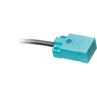


These CJF inductive proximity sensors combine flat PBT cases, mounting openings and a red operation indicator. Select the 5mm, 6mm or 7mm sensing range, then match the setting distance and output circuit to the installation. The listed models use 10-30VDC and IP67 construction. Check the sensing target, surrounding metal and sensor spacing when arranging contactless position detection.
| Model group | NPN three-wire | PNP three-wire | DC two-wire |
|---|---|---|---|
| CJF10-05 | CJF10-05DNA CJF10-05DNB | CJF10-05DPA CJF10-05DPB | CJF10-05DLA |
| CJF11-06 | CJF11-06DNA CJF11-06DNB | CJF11-06DPA CJF11-06DPB | CJF11-06DLA |
| CJF12-07 | CJF12-07DNA CJF12-07DNB | CJF12-07DPA CJF12-07DPB | CJF12-07DLA |
D identifies the 10-30VDC supply, N identifies NPN, P identifies PNP and L identifies DC two-wire. Final A means NO and B means NC. The listed two-wire selection contains NO models.
| Model group | Sensing distance | Setting distance | Standard iron target | Average response frequency |
|---|---|---|---|---|
| CJF10-05 | 5mm | 0-3.5mm | 25×25×1mm | 500Hz |
| CJF11-06 | 6mm | |||
| CJF12-07 | 7mm | 0-5.5mm | 400Hz |
Response frequency is an average measured with the standard target, target spacing twice the standard target width and a sensing gap equal to half the nominal sensing distance.
| Parameter | DC three-wire | DC two-wire |
|---|---|---|
| Supply | 10-30VDC | |
| Residual voltage | Maximum 1V | Maximum 3.5V |
| Leakage current | Maximum 10mA | |
| Control output | Maximum 200mA | |
| Hysteresis | Maximum 10% of sensing distance | |
| Temperature effect | Within ±10% of sensing distance over -25°C to +70°C, referenced to +20°C | |
| Insulation resistance | At least 50MΩ at 500VDC | |
| Dielectric strength | 1500VAC, 50/60Hz, for 1 minute | |
| Vibration resistance | 1mm amplitude, 10-55Hz with a 1 minute cycle; 2 hours in each X, Y and Z direction | |
| Shock resistance | 500m/s², approximately 50G; three shocks in each X, Y and Z direction | |
| Indicator | Red operation LED | |
| Operating temperature | -25°C to +70°C, without icing | |
| Storage temperature | -30°C to +80°C, without icing | |
| Humidity | 35-95%RH, without condensation | |
| Protection circuits | Surge, reverse polarity and overcurrent protection, including overload and short-circuit protection | |
| Case | PBT | |
| Standard cable | Gray PVC | |
| Enclosure protection | IP67 | |
| Circuit | Standard cable | Connection |
|---|---|---|
| NPN three-wire | Ø3.8mm, three conductors, 2m | Brown: positive supply; blue: 0V; black: output. Load between positive supply and black output. |
| PNP three-wire | Brown: positive supply; blue: 0V; black: output. Load between black output and 0V. | |
| DC two-wire | Ø3.8mm, two conductors, 2m | Brown and blue active leads; load in series with the sensor. |
Conductor-construction references are AWG22 designation, 25 strands of Ø0.1mm per conductor and Ø1.25mm insulation outside diameter. The attachment includes the output-circuit and NO/NC timing diagrams.

| Position | Selection | Code | Meaning and limits |
|---|---|---|---|
| 1 | Classification | CJ | Inductive proximity sensor |
| 2 | Shape | F | Flat square housing |
| 3 | Housing group | 10, 11, 12 | CJF10, CJF11 and CJF12; use their actual dimensions below |
| 4 | Version | Omitted | Standard form |
| 5 | Distance | 05, 06, 07 | 5mm, 6mm and 7mm respectively |
| 6 | Supply | A | 90-250VAC configuration |
| D | 10-30VDC; used by the listed models | ||
| E | 20-60VDC configuration | ||
| J | 5-10VDC configuration | ||
| 7 | Output circuit | N | NPN |
| P | PNP | ||
| K | AC two-wire configuration | ||
| L | DC two-wire | ||
| 8 | Output state | A | NO |
| B | NC | ||
| C | Combined NO+NC configuration; no full C-suffix model is included in the selection table above | ||
| 9 | Connection | Omitted | Cable with free leads |
| M | Direct M12 straight four-pin A-coded connector | ||
| M plus connector-selection code | M-type cable connector | ||
| D plus connector-selection code | DT-type connector | ||
| A plus connector-selection code | AMP-type connector | ||
| S plus connector-selection code | SM-type connector | ||
| 10 | Cable material | Omitted | PVC |
| U | PUR | ||
| VP | Shielded PVC | ||
| UP | Shielded PUR | ||
| 11 | Cable length | L1-L5 | L1 = 1m, through L5 = 5m; other lengths can be specified. Standard cables are 2m. |
Specify a complete matching configuration for alternative supply, output and connection options. The listed model specifications apply to the 10-30VDC selection.
| Model group | Body dimensions | Mounting references |
|---|---|---|
| CJF10-05 | 30mm by 18mm by 11mm; Ø3.8mm cable | 25.2mm length reference; 12.6mm opening-spacing reference; 2.1mm feature detail |
| CJF11-06 | 50mm by 25mm by 10mm; Ø3.8mm cable | 42.5mm length reference; 15mm opening-spacing reference; two Ø4.6mm mounting features |
| CJF12-07 | 45mm by 30mm by 12mm; Ø3.8mm cable | 35.6mm length reference; 18mm opening-spacing reference; two Ø4.6mm mounting features |
The attachment identifies the indicator, opening shape and dimension endpoints for each housing.
| Illustrated arrangement | Distance shown | Installation requirement |
|---|---|---|
| Sensors facing each other | 108mm | Maintain the spacing between the reference planes shown in the attachment to reduce mutual interference. |
| Parallel sensors | 80mm | |
| Surrounding metal at sensing-head height | 5mm lateral clearance | Keep metal outside the illustrated sensing-head clearance. |
| Sensing head below surrounding metal | 5mm at each side; 15mm above the sensing head in the illustrated arrangement | Use the recessed-mounting geometry shown in the attachment. |
Use the diagram's measurement endpoints when laying out the installation; the dimensions refer to its illustrated geometry.
| Reference | Standard | Documentation |
|---|---|---|
| CCC | GB/T 14048.10 | Obtain documents for the exact model and electrical configuration. |
| TUV | EN 60947-5-2 | |
| CE |
| Utilization category | Reference rating | Model scope |
|---|---|---|
| AC-140 | 200mA at 24-250VAC | Reference category; the listed models use a DC supply |
| DC-13 | 200mA at 10-30VDC | Operating range of the listed DC models |
The range is intended for ordinary industrial control. Nuclear, gas or power systems requiring exceptional reliability, personal-safety functions, harsh outdoor or contaminated environments, fire or explosion hazards, military use and aerospace require a specifically designed and confirmed configuration.
