


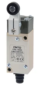


| Part Number: | CHL-5 | 030 | - | M |
|---|---|---|---|---|
| Explanation: |
Series CHL-5 - Metal body vertical limit switch series prefix |
Actuator 000 - Fixed roller lever |
Roller material NONE - Standard resin roller; omit M and the preceding hyphen |
CHL vertical limit switches use a metal enclosure, rubber cable-entry sleeve and double-spring contact mechanism. All ten configurations have IP65 protection and snap-action 1NO+1NC contacts. Sealed plungers suit direct linear actuation, roller and rod levers provide rotary actuation, and flexible spring heads accommodate targets approaching from different lateral directions.
| Model | Actuator | Dimensions and adjustment |
|---|---|---|
| CHL-5100 | Sealed plunger | Ø8mm stainless plunger |
| CHL-5200 | Sealed transverse roller plunger | Ø12.6×3.8mm stainless roller |
| CHL-5220 | Sealed vertical roller plunger | |
| CHL-5000 | Fixed roller lever | Ø18×6.8mm resin roller; lever orientation adjustable through 360°; head mounts in four directions |
| CHL-5050 | Adjustable rod lever | Ø3×160mm stainless rod; head mounts in four directions |
| CHL-5030 | Adjustable roller lever | Ø18×6.8mm resin roller; radius 30–75mm; head mounts in four directions |
| CHL-5391 | Adjustable rubber roller lever | Ø50×8.3mm roller; radius 40–75mm; head mounts in four directions |
| CHL-5300 | Coil spring with plastic tip | 110±2.5mm head dimension; 38mm tip |
| CHL-5330 | Flexible whisker | 110±2.5mm head dimension |
| CHL-5381 | Coil spring |
The common body is 33mm wide with a 60.7mm body-height dimension. Mounting centers are 24±0.2mm horizontally and 50±0.2mm vertically, with Ø4.2mm mounting holes. Use the attached model drawings for depth, actuator projection and cable-entry clearance.
The fixed series prefix CHL-5 is followed directly by a three-digit actuator code. CHL-5030 is the standard adjustable resin roller model; CHL-5030-M adds the optional metal roller. The -M option is available only for CHL-5000 and CHL-5030. Its hyphen is retained as a separate ordering separator.
| Segment | Code | Meaning |
|---|---|---|
| Series prefix | CHL-5 | Metal body vertical limit switch family |
| Actuator | 000 | Fixed roller lever |
| 030 | Adjustable roller lever | |
| 050 | Adjustable rod lever | |
| 100 | Sealed plunger | |
| 200 | Sealed transverse roller plunger | |
| 220 | Sealed vertical roller plunger | |
| 300 | Coil spring with plastic tip | |
| 330 | Flexible whisker | |
| 381 | Coil spring | |
| 391 | Adjustable rubber roller lever | |
| Roller material, codes 000 and 030 only | Omitted | Standard resin roller; no suffix or final hyphen |
| -M | Optional metal roller |
| Parameter | Value |
|---|---|
| Contact arrangement | 1NO+1NC, snap action; NO terminals 13–14, NC terminals 11–12 |
| Operating speed | 5mm/s–0.5m/s |
| Electrical switching frequency | 30 operations/min |
| Initial contact resistance | 25mΩ maximum |
| Insulation resistance | 100MΩ minimum at 500VDC |
| Minimum load | 24VDC, 10mA |
| Rated insulation voltage Ui | 380V |
| Rated impulse withstand voltage Uimp | 2.5kV |
| Conventional thermal current Ith | 10A |
| Enclosure protection | IP65 |
| Vibration | 10–55Hz; 1.5mm double amplitude |
| Shock, mechanical durability | 1,000m/s² |
| Shock, malfunction resistance | 300m/s² |
| Operating temperature | -20°C to +70°C, no icing |
| Humidity | Below 95%RH |
| Dielectric test location | Test voltage | Frequency and duration |
|---|---|---|
| Between open terminals of the same polarity | 1,000VAC | 50/60Hz for 1 minute |
| Between current-carrying and non-current-carrying metal | 1,500VAC | |
| Between each terminal and ground |
| Resistive-load test condition | Electrical endurance |
|---|---|
| 240VAC, 3A | More than 500,000 operations |
| 250VAC, 6A | More than 300,000 operations |
Endurance test conditions, continuous thermal current and rated load categories serve different purposes. An endurance test current does not replace the applicable switching rating.
| Voltage | Non-inductive loads | Inductive loads | ||||||
|---|---|---|---|---|---|---|---|---|
| Resistive | Lamp | Inductive | Motor | |||||
| NC | NO | NC | NO | NC | NO | NC | NO | |
| 125VAC | 5A | 1.5A | 0.7A | 3A | 2A | 1A | ||
| 250VAC | 5A | 1A | 0.5A | 3A | 1.5A | 0.8A | ||
| 12VDC | 5A | 3A | 4A | 3A | ||||
| 24VDC | ||||||||
| 125VDC | 0.4A | — | — | — | ||||
| 250VDC | 0.2A | |||||||
These values represent steady-state currents. The inductive-load condition is an AC power factor of 0.4 or a DC time constant below 7ms. Lamp loads assume inrush up to ten times running current; motor loads assume six times running current. A dash means no rating is stated.
| Contact | Maximum inrush current |
|---|---|
| NC | 24A |
| NO | 12A |
| Utilization category | Rated current | Rated voltage |
|---|---|---|
| AC-15 | 6A | 250V |
| DC-13 | 0.3A | 220V |
| Declared conformity reference | Standard |
|---|---|
| CCC | GB/T14048.5 |
| CE | EN60947-5-1 |
Obtain configuration-specific documentation where certification evidence is required.
OF is maximum operating force, RF minimum release force, PT pretravel, OT minimum overtravel, MD movement differential and OP operating position. Plunger PT and MD are maximum values; lever and spring PT is specified as 15±5°. Lever MD is a maximum; spring MD is specified as 10±2°.
| Models | OF | RF | PT | OT | MD | OP |
|---|---|---|---|---|---|---|
| CHL-5100, CHL-5200, CHL-5220 | 8.8N | 1.47N | 1.8mm maximum | 4mm | 1.2mm maximum | 40±0.8mm |
| CHL-5000, CHL-5050, CHL-5030, CHL-5391 | 7.35N | 0.98N | 15±5° | 75° | 12° maximum | — |
| CHL-5300, CHL-5330, CHL-5381 | 1.47N | — | 15±5° | — | 10±2° | — |
CHL-5030 and CHL-5391 operating characteristics use a stated 31.2mm test arm. This test condition is distinct from the installed roller adjustment range. Flexible heads can bend in lateral directions; do not actuate them by pushing down along the axis. Apply the target within the upper one-third of the actuator length. CHL-5300, CHL-5330 and CHL-5381 remain separate configurations despite their shared operating values.
Use the exact model drawing to set the target path, mounting clearance and permitted travel. Secure the cable-entry seal to maintain enclosure protection. Personnel protection, high-reliability continuous systems, harsh outdoor or chemical environments, explosive atmospheres, nuclear, aerospace and military service require a separate application assessment.
