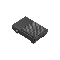


| Part Number: | CFS | - | 2 | - | U | L2 | - | F |
|---|---|---|---|---|---|---|---|---|
| Explanation: |
Series CFS - Medium metal foot switch series |
Pedal Structure 1 - Iron housing, self-resetting, CMV16-001C2, 10A, 0.5mm² three-core cable |
Cable Material Blank - PVC cable; omit this code |
Cable Length L1 - 1m cable |
Special Configuration Blank - Conventional single pedal; omit the optional suffix and its preceding separator |
These metal foot switches provide self-resetting pedal control in three housing shapes. CFS-1 uses an iron shell; CFS-2 and CFS-3 use aluminum-alloy housings. CFS-3S fits a CM-1704 switch for the 15A configuration. A cable gland secures the cable outlet. Select the housing, internal switch and cable before choosing a single or multiple-pedal assembly.
| Structure | Housing | Action | Built-in switch | Contacts | Rated current | Cable conductor area | Operating force |
|---|---|---|---|---|---|---|---|
| CFS-1 | Iron | Self-resetting | CMV16-001C2 | 1NO+1NC | 10A | 0.5mm², three-core | ≤25N |
| CFS-2 | Aluminum alloy | ||||||
| CFS-3 | 0.75mm², three-core | ||||||
| CFS-3S | CM-1704 | 15A |
The standard ordering examples use 2m black cable. Cable color options include beige or black; specify the required color with the cable material and assembly. The complete pedal enclosure is IP20. The F option specifies a custom waterproof internal switch and does not establish an IP67 rating for the complete pedal.
| Parameter | Specification |
|---|---|
| Contact resistance | Below 50mΩ, initial value |
| Insulation resistance | At least 100MΩ at 500VDC |
| Minimum working load | 24VDC, 10mA |
| Dielectric strength | 1500VAC for 1 minute |
| Electrical durability | More than 100,000 operations at 240VAC, 3A resistive load |
| Ambient temperature | -25°C to +70°C, without condensation or icing |
| Ambient humidity | 45-85%RH |
| Protection | IP20, IEC/EN 60529 |
| AC-15 rating | 10A at 250VAC; the selected internal switch retains its model-specific current rating |
| Reference designation | Standard | Documentation |
|---|---|---|
| CCC | GB/T 14048.5 | Check the documentation applicable to the selected model and configuration. |
| CE | EN 60947-5-1 |
| Segment | Code | Meaning |
|---|---|---|
| Series | CFS | Medium metal foot switch family |
| Structure | 1 | Iron housing, CMV16-001C2, self-resetting; 0.5mm² three-core black cable |
| 2 | Aluminum-alloy housing, CMV16-001C2, self-resetting; 0.5mm² three-core black cable | |
| 3 | Aluminum-alloy housing, CMV16-001C2, self-resetting; 0.75mm² three-core black cable | |
| 3S | Aluminum-alloy housing, CM-1704, self-resetting; 0.75mm² three-core black cable | |
| Cable material | Omitted | PVC cable |
| U | Oil-resistant PUR cable | |
| Cable length | L1-L5 | 1m to 5m, with L1 meaning 1m and L2 meaning 2m. Other cable lengths can be specified. |
| Special configuration | Omitted | Conventional single pedal |
| F | Custom waterproof built-in microswitch, internal switch IP67 only | |
| T2, T3, T4 | Two-, three- or four-pedal assembly | |
| FT2, FT3, FT4 | Custom two-, three- or four-pedal assembly with waterproof built-in switches |
Suffix punctuation depends on the structure: the CFS-1 examples attach F or T2 directly to L2, while CFS-2 and CFS-3 waterproof examples use a hyphen before F. The displayed CFS-2 ordering example follows that structure. Confirm the mechanical assembly when selecting multiple pedals.
| Model | Action and internal switch | Contacts | Current | Standard cable | Operating force |
|---|---|---|---|---|---|
| CFS-1-L2 | Self-resetting, CMV16-001C2 | 1NO+1NC | 10A | 0.5mm², three-core, 2m, black | ≤25N |
| CFS-1-L2F | Custom waterproof internal microswitch | ||||
| CFS-1-L2T2 | Self-resetting, CMV16-001C2 in each pedal | 2 × (1NO+1NC) | 10A per switch | ||
| CFS-1-L2T3 | 3 × (1NO+1NC) | ||||
| CFS-1-L2T4 | 4 × (1NO+1NC) | ||||
| CFS-2-L2 | Self-resetting, CMV16-001C2 | 1NO+1NC | 10A | 0.5mm², three-core, 2m, black | |
| CFS-2-L2-F | Custom waterproof internal microswitch | ||||
| CFS-3-L2 | Self-resetting, CMV16-001C2 | 0.75mm², three-core, 2m, black | |||
| CFS-3S-L2 | Self-resetting, CM-1704 | 15A | |||
| CFS-3-L2-F | Custom waterproof internal microswitch | 10A |
| Structure | Dimensions | Mounting details |
|---|---|---|
| CFS-1 | 103mm × 67mm × 28.5mm | Rectangular iron pedal housing |
| CFS-2 | 135mm overall length; 124mm reference length; 66mm width; 43mm height | Three Ø5mm holes; 52mm transverse spacing |
| CFS-3, CFS-3S | 172mm overall length; 160mm reference length; 85mm width; 61mm height | Three Ø6mm holes; 48mm transverse spacing |
| CFS-1-L2T2 | 204mm × 156mm base; 32mm section height | Two Ø4mm holes; 24±0.2mm pedal spacing |
| CFS-1-L2T3 | 306mm × 156mm base; 32mm section height | Four Ø4mm holes; 24±0.2mm pedal spacing |
Check the dimensional drawings in the attachment for the mounting view and the dimensions associated with each feature.
Standard contacts require a working load of at least 24VDC, 10mA. Specify a small-load configuration for lower loads. Do not reuse contacts previously assigned to general loads for a smaller-load circuit. Use suitable contact protection for switching surges and an appropriate suppression circuit where contact bounce causes control disturbances.
The pedals are intended for ordinary industrial control. Nuclear, gas or power systems requiring exceptional reliability, personal-safety functions, harsh outdoor or contaminated environments, fire or explosion hazards, military use and aerospace require a specifically designed and confirmed configuration.
