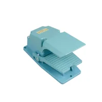

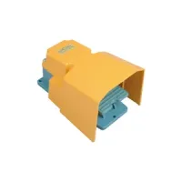
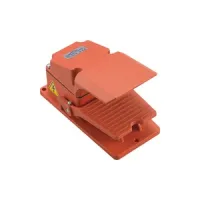



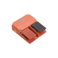

| Part Number: | CFS | - | 302 | P | - | U | L2 | - | T2 |
|---|---|---|---|---|---|---|---|---|---|
| Explanation: |
Series CFS - Heavy duty aluminum-alloy foot switch family |
Pedal Structure 302 - Covered pedal, one CM-1704 momentary switch |
Conduit Entry Blank - M20 entry; omit this code |
Cable Material Blank - PVC cable for a prewired version; omit this code |
Cable Length Blank - Standard version without cable; omit the cable block and its redundant separator |
Pedal Assembly Blank - Conventional single unit; omit the suffix and its separator |
This aluminum-alloy foot switch family includes covered, open and hooded pedals, metal-base variants, and two-pedal units. Select the pedal structure and internal switching mechanism together: momentary models return when released, while the 305, 405 and 505 variants use alternate-action latching switches. The M suffix identifies a metal base. A cable gland secures the cable outlet.
| Structure codes | Pedal form | Action | Internal switching mechanism | Contact arrangement | Current per switch | Operating force per pedal |
|---|---|---|---|---|---|---|
| 302, 302M | Covered | Momentary, self-resetting | One CM-1704 | 1NO+1NC | 15A | ≤35N |
| 304, 304M | Two CM-1704 | 2 × (1NO+1NC) | ||||
| 305, 305M | Latching, alternate action | One CMV16-071C2 | 1NO+1NC | 10A | ||
| 402, 402M | Open | Momentary, self-resetting | One CM-1704 | 1NO+1NC | 15A | |
| 404, 404M | Two CM-1704 | 2 × (1NO+1NC) | ||||
| 405, 405M | Latching, alternate action | One CMV16-071C2 | 1NO+1NC | 10A | ||
| 502, 502M | Hooded | Momentary, self-resetting | One CM-1704 | 1NO+1NC | 15A | |
| 504, 504M | Two CM-1704 | 2 × (1NO+1NC) | ||||
| 505, 505M | Latching, alternate action | One CMV16-071C2 | 1NO+1NC | 10A | ||
| 5G | Rounded hood | Momentary, self-resetting | One CM-1306 | 1NO+1NC | 15A | |
| 54G | Two CM-1306 | 2 × (1NO+1NC) | ||||
| 602 | Hooded two-pedal unit | Two contact modules | 2 × (1NO+1NC), complete unit | 16A | ||
| 902 | Open two-pedal unit |
Codes with M retain the listed contact mechanism and action, with a metal base. A guard describes the mechanical housing; it does not establish a safety-control performance level.
| Parameter or version | Specification and conditions |
|---|---|
| Housing | Aluminum alloy with coated exterior |
| Contact resistance | Below 50mΩ, initial value |
| Insulation resistance | At least 100MΩ at 500VDC |
| Minimum working load | 24VDC, 10mA |
| Dielectric strength | 1890VAC for 1 minute |
| Electrical durability at a stated load | More than 100,000 operations at 240VAC, 3A resistive load |
| General electrical durability | More than 300,000 operations; load condition is not specified for this figure |
| CFS-GM35, CFS-GM45, CFS-HM55 | More than 100,000 operations; named-version exception, without a specified load condition |
| Ambient temperature | -25°C to +70°C, without condensation or icing |
| Ambient humidity | 45-85%RH |
| Captured CFS structure codes | IP50 |
| Versions marked CFS-HM5G or CFS-HM54G | IP66; do not apply this named-version rating to a differently marked CFS-5G or CFS-54G unit |
| AC-15 reference rating | 15A at 250VAC for the 15A configurations; 16A at 250VAC for the two-module 16A configurations. Follow the selected 10A latching switch's own rating. |
| Reference designation | Standard | Documentation |
|---|---|---|
| CCC | GB/T 14048.5 | Check documentation for the exact model, marking and configuration. |
| CE | EN 60947-5-1 |
| Segment | Code | Meaning and dependency |
|---|---|---|
| Series | CFS | Heavy duty aluminum-alloy foot switch family |
| Structure | 302-505, M variants, 5G, 54G, 602, 902 | Choose one complete structure code from the selection table; the codes between 302 and 505 are the explicitly listed variants, not every intervening number |
| Conduit entry | Omitted | M20 |
| P | PG13.5 | |
| Cable material | Omitted | PVC cable when a prewired version is selected |
| U | Oil-resistant PUR cable; combine with a cable-length code | |
| Cable length | Omitted | Standard version without cable |
| L1-L5 | 1m to 5m, with L1 meaning 1m and L2 meaning 2m; other lengths can be specified | |
| Special assembly | Omitted | Conventional single unit |
| T2 | Two pedals | |
| T3 | Three pedals | |
| T4 | Four-pedal option; confirm the layout for the chosen structure |
For unwired models, omit the unused cable block and its redundant separator. For a conventional unit, omit the optional assembly suffix and its separator. Cable conductor area is a configuration detail and must be specified with the required cable.
In the following table, contact totals count all pedals. The operating force is ≤35N per pedal, and current is rated per internal switch.
| Base structure | Two-pedal example | Total contacts, T2 | Three-pedal example | Total contacts, T3 | Action and switches per pedal | Current per switch |
|---|---|---|---|---|---|---|
| 302 | CFS-302-T2 | 2 × (1NO+1NC) | CFS-302-T3 | 3 × (1NO+1NC) | Momentary; one CM-1704 | 15A |
| 304 | CFS-304-T2 | 4 × (1NO+1NC) | CFS-304-T3 | 6 × (1NO+1NC) | Momentary; two CM-1704 | |
| 305 | CFS-305-T2 | 2 × (1NO+1NC) | CFS-305-T3 | 3 × (1NO+1NC) | Latching; one CMV16-071C2 | 10A |
| 402 | CFS-402-T2 | 2 × (1NO+1NC) | CFS-402-T3 | 3 × (1NO+1NC) | Momentary; one CM-1704 | 15A |
| 404 | CFS-404-T2 | 4 × (1NO+1NC) | CFS-404-T3 | 6 × (1NO+1NC) | Momentary; two CM-1704 | |
| 405 | CFS-405-T2 | 2 × (1NO+1NC) | CFS-405-T3 | 3 × (1NO+1NC) | Latching; one CMV16-071C2 | 10A |
| 502 | CFS-502-T2 | 2 × (1NO+1NC) | CFS-502-T3 | 3 × (1NO+1NC) | Momentary; one CM-1704 | 15A |
| 504 | CFS-504-T2 | 4 × (1NO+1NC) | CFS-504-T3 | 6 × (1NO+1NC) | Momentary; two CM-1704 | |
| 505 | CFS-505-T2 | 2 × (1NO+1NC) | CFS-505-T3 | 3 × (1NO+1NC) | Latching; one CMV16-071C2 | 10A |
| Metal-base structure | Two-pedal example | Three-pedal example | Switch per pedal | Contacts per pedal | Complete-assembly contacts | Current per switch |
|---|---|---|---|---|---|---|
| 302M | CFS-302M-T2 | CFS-302M-T3 | One CM-1704, momentary | 1NO+1NC | T2: 2 × (1NO+1NC) T3: 3 × (1NO+1NC) | 15A |
| 402M | CFS-402M-T2 | CFS-402M-T3 | ||||
| 502M | CFS-502M-T2 | CFS-502M-T3 |
| Structure or assembly | Dimensions and reference features |
|---|---|
| 302, 304, 305 and M versions | 200mm overall length, 103.2mm overall width, 130mm overall height; 186mm mounting reference, 86mm reference width, 101mm inner base width, 68mm cover clearance; three Ø7mm mounting holes |
| 402, 404, 405 and M versions | 200mm × 103.2mm × 77.5mm; 186mm mounting reference; three Ø7mm holes |
| 502, 504, 505 and M versions | 207mm × 149mm × 133mm; 130mm hood width, 101mm inner base width, 65mm hood clearance, 186mm mounting reference; three Ø7mm holes |
| 302-T2, 302M-T2 | 210mm × 205mm base; six M5 mounting holes; 86mm and 98mm transverse references; 90mm upper section height, 140mm complete side-view length |
| 302-T3, 302M-T3 | 315mm × 205mm base; nine M5 mounting holes; same 86mm and 98mm transverse references |
| 402-T2, 402M-T2 | 210mm × 205mm base; six M5 mounting holes; 85mm side-view height |
| 402-T3, 402M-T3 | 315mm × 205mm base; nine M5 mounting holes; 85mm side-view height |
| 502-T2, 502M-T2 | 310mm × 207mm base; 130mm side-view height; 186mm mounting reference and 86mm pedal reference width |
| 502-T3, 502M-T3 | 470mm × 207mm base; same 130mm side-view height, 186mm mounting reference and 86mm pedal reference width |
| 602 | 216mm length, 235mm overall width, 156mm overall height; 220mm hood width, 95mm inner clearance, 185mm reference length |
| 902 | 213mm × 180mm × 65mm |
| 5G, 54G | 228mm overall length, 157mm overall width, 145mm overall height; 185mm mounting reference, 140mm hood width, 85mm hood clearance, 100mm and 102mm inner width references; three Ø8mm holes |
Use the dimensional drawings in the attachment to identify the feature associated with each reference dimension.
For standard contacts, use loads of at least 24VDC, 10mA. Specify a small-load contact configuration below that level. Contacts previously used for general loads should not subsequently serve a smaller-load circuit. Use appropriate contact protection for switching surges and a suitable suppression circuit where contact bounce causes control disturbances.
These switches are intended for ordinary industrial control. Nuclear, gas or power systems requiring exceptional reliability, personal-safety functions, harsh outdoor or contaminated environments, fire or explosion hazards, military use and aerospace require a specifically designed and confirmed configuration.
