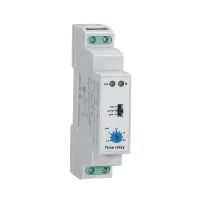
| Part Number: | CDT6 | - | LS | 2 | 16 | S |
|---|---|---|---|---|---|---|
| Explanation: |
Product Family CDT6 - DIN rail time relay |
Series LS - Corridor and staircase lighting delay switch |
Function Configuration 2 - Documented corridor switch configuration with one normally open output, one end internally connected to L |
Contact Current Rating 10 - Additional 10A option defined in the ordering guide |
Power Supply S - 100–240VAC, 50–60Hz |
CDT6-LS controls corridor or staircase lighting with ON, AUTO and OFF modes. AUTO provides an adjustable 0.5–20min delay, while ON holds the output closed and OFF holds it open. The 18mm-wide switch mounts on a 35mm DIN rail and supports illuminated pushbuttons.
The common model CDT6-LS216S operates from 100–240VAC and has one normally open output with one end internally connected to L. Terminal 4 supplies the switched line to the load; this output shares the device's line connection.

| Field | Codes and meaning |
|---|---|
| Family | CDT6: DIN rail time relay |
| Series | LS: corridor delay switch |
| Function code | 2: corridor switch configuration with one normally open output internally linked to L |
| Contact rating | 16: documented 16A common model; 10: additional 10A option in the ordering guide |
| Supply | S: 100–240VAC; A–Z letter combinations: custom voltage |
| Common model | Output | Contact Ith / Ie | Supply |
|---|---|---|---|
| CDT6-LS216S | One NO contact, internally linked to L | 16A / 5A | 100–240VAC, 50–60Hz |
| Mode | Operation |
|---|---|
| ON | Output remains closed while the device is supplied. |
| AUTO | Pushbutton-controlled timed lighting, with t set from 0.5 to 20min by the knob. |
| OFF | Output remains open. |

| Characteristic | Specified value |
|---|---|
| Supply / terminals | 100–240VAC, 50–60Hz; L–N |
| Power consumption | Maximum 6VA / 1.3W |
| Supply tolerance | −15% to +10% |
| AUTO delay / setting | 0.5–20min; front knob |
| Setting accuracy / repeatability | 10% / 0.2% |
| Temperature influence | 0.05%/°C, referenced to 20°C |
| Output construction | One normally open contact; one end internally connected to L |
| Contact rating data | 16A, AC-1; contact data list 250VAC/24VDC. The complete device's specified supply is 100–240VAC. |
| Minimum switching power | 500mW |
| Power / output indication | Green LED / red LED |
| Neon pushbutton connections | N–3 or L–3, according to the selected connection scheme |
| Maximum neon pushbuttons | 75 at 230VAC, based on approximately 0.68mA per neon indicator |
| Neon circuit current in wiring diagrams | Maximum 50mA |
| Mechanical / electrical life | 10,000,000 mechanical operations; 100,000 electrical operations with resistive load |
| Reset time | Maximum 200ms |
| Operating temperature | −20°C to +55°C |
| Storage / transport temperature | −35°C to +75°C |
| Mounting / orientation | 35mm DIN rail; any orientation |
| Protection / pollution degree | IP20 / 2 |
| Maximum altitude | 2000m |
| Conductors / tightening torque | One 2.5mm² conductor or two 1.5mm² conductors; 0.4N·m |
| Dimensions / weight | 90mm high × 18mm wide × 65mm deep; 61g |

| Illustrated lighting load | Maximum load in the selection document |
|---|---|
| Incandescent lamp | 2000W |
| Linear halogen lamp | 2000W |
| Fluorescent lamps without the illustrated parallel compensation capacitor | 1000W |
| Compensated fluorescent lamp circuit | 900W, 125µF |
| Compact fluorescent lamp | 400W |
| LED lamp | 300W |


Select the load from the relevant lighting category and observe the neon indicator current limit. The selection document supplies the operating and wiring information above; request the applicable certification evidence from CNTD when required.
The manufacturer requires specially designed equipment and written confirmation for high reliability energy systems, applications involving personal safety or major property risk, harsh or outdoor environments, fire or explosion risks, and military or aerospace use.
