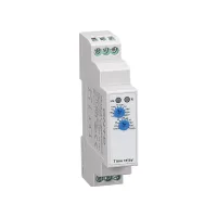

| Part Number: | CDT6 | - | A | 1 | 10 | M |
|---|---|---|---|---|---|---|
| Explanation: |
Product Family CDT6 - DIN rail time relay |
Timing Function A - Power-on delay |
Contact Arrangement 1 - One timed changeover contact |
Contact Current Rating 10 - 10A contacts; AC-15 operational rating 2.5A at 250VAC |
Power Supply M - 220VAC, 50–60Hz |
CDT6-A/B time relays provide knob-set timing for control circuits, including heater operating time, pump operation and fan disconnection sequences. Choose A for power-on delay or B for delayed disconnection, then select the contact arrangement, contact rating and supply. The 18mm-wide housing mounts on a 35mm DIN rail.
The range includes one timed changeover contact, two timed changeover contacts, or one timed contact plus one instantaneous contact. Eight timing ranges cover 0.1s to 10 days; separate ON and OFF positions complete the ten-position range selector. Green and red LEDs indicate power and relay output respectively.

| Field | Codes and meaning |
|---|---|
| Product family | CDT6: DIN rail time relay |
| Timing function | A: power-on delay; B: delayed disconnection |
| Contact arrangement | 1: one timed changeover contact; 2: two timed changeover contacts; T: one timed changeover plus one instantaneous changeover contact |
| Contact rating | 10: 10A; 16: 16A |
| Supply | M: 220VAC; W: 12–240VAC/DC; A–Z letter combinations: custom voltage. AC versions operate at 50–60Hz. |
| Function | Contact arrangement | 10A, 220VAC model | 16A, 12–240VAC/DC model |
|---|---|---|---|
| A: power-on delay | One timed changeover | CDT6-A110M | CDT6-A116W |
| Two timed changeovers | CDT6-A210M | CDT6-A216W | |
| One timed plus one instantaneous changeover | CDT6-AT10M | CDT6-AT16W | |
| B: delayed disconnection | One timed changeover | CDT6-B110M | CDT6-B116W |
| Two timed changeovers | CDT6-B210M | CDT6-B216W | |
| One timed plus one instantaneous changeover | CDT6-BT10M | CDT6-BT16W |
These are the twelve common full models in the selection document. The six web model labels CDT6-A1, CDT6-A2, CDT6-AT, CDT6-B1, CDT6-B2 and CDT6-BT identify function/contact arrangements; use the complete ordering code to specify supply and current rating.
| Contact rating category | 10A version | 16A version |
|---|---|---|
| Output contact rating | 10A at 250VAC/24VDC | 16A at 250VAC/24VDC |
| Common-model Ith / Ie values | 10A / 2.5A | 16A / 5A |
| AC-15 rated operational current at 250VAC | 2.5A | 5A |
| Number of contacts | 1 arrangement: one changeover; 2 or T arrangement: two changeovers, with timing behavior determined by the selected arrangement | |


| Timing characteristic | Value |
|---|---|
| Setting method | Front-panel knobs |
| Overall timing range | 0.1s to 10 days |
| Setting accuracy | 10% |
| Repeatability | 0.2% |
| Temperature influence | 0.05%/°C, referenced to 20°C |
| Reset time | Maximum 200ms |
| Characteristic | Specification |
|---|---|
| Supply terminals | A1–A2 |
| W supply | 12–240VAC/DC; 50–60Hz for AC |
| W power consumption | 0.09–3VA on AC; 0.05–1.7W on DC |
| M supply | 220VAC, 50–60Hz |
| M consumption, A1/B1 | Maximum 6VA / 1.3W |
| M consumption, A2/B2/AT/BT | Maximum 6VA / 1.9W |
| Allowable supply variation | −15% to +10% |
| Minimum switching power | 500mW |
| Power / output indication | Green LED / red LED |
| Mechanical life | 10,000,000 operations |
| Electrical life, resistive load | 100,000 operations |
| Operating temperature | −20°C to +55°C |
| Storage and transport temperature | −35°C to +75°C |
| Mounting / orientation | 35mm DIN rail; any orientation |
| Protection / pollution degree | IP20 / 2 |
| Installation altitude | No more than 2000m |
| Conductors and tightening torque | One 2.5mm² conductor or two 1.5mm² conductors; 0.4N·m |
| Dimensions | 90mm high × 18mm wide × 65mm deep |
| Weight | A1/B1: 67g; A2/B2/AT/BT: 80g |


The selection document lists CCC with GB/T14048.5 and CE with EN60947-5-1. Certificate document numbers are available from CNTD. Match the load to its applicable duty rating and the ordered contact version.
The manufacturer requires specially designed products and written confirmation for high reliability energy systems, applications involving personal safety or major property risk, harsh or outdoor environments, fire or explosion risks, and military or aerospace use.
