
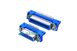
ULO-CC427 provides straight PCB termination in male and female configurations. ULO-CC467 provides a female interface with right-angle PCB solder tails and a choice of latch support. Select the contact count, connector gender and mounting dimensions for the intended assembly.
| Model selection | CC427 | CC467 |
|---|---|---|
| PCB termination | Straight | Right-angle |
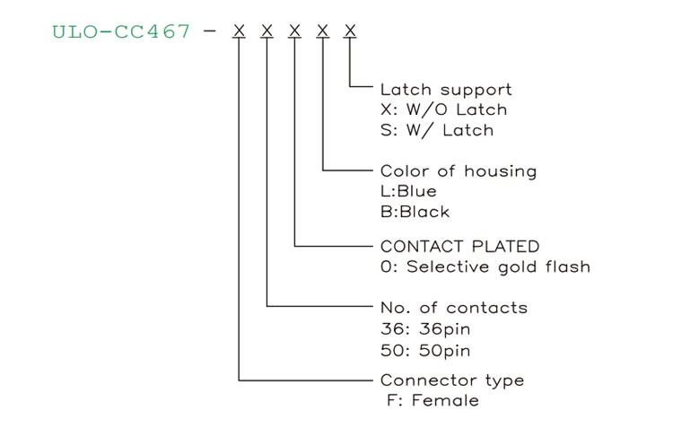
| Connector type | M: male; F: female | F: female |
| Total contacts | 14, 24, 36, 50 | 36, 50 |
| Housing colour | L: blue; W: white; B: black | L: blue; B: black |
| Contact plating | 8: full gold flash; 0: selective gold flash; 1: selective 10µin gold; 3: selective 30µin gold | 0: selective gold flash |
| Latch selection | No separate ordering field listed | X: without latch; S: with latch |
| Operating temperature | -20°C to +80°C | -20°C to +105°C |
| Insulator | Thermoplastic | PBT with 30% glass fibre |
CC427 orders the contact count before gender; CC467 orders gender before the contact count. Use each model's ordering sequence and keep its colour, plating and latch selections separate.

| Characteristic | Both models |
|---|---|
| Rated current | 3A |
| Contact impedance | ≤50mΩ |
| Insulation impedance | 1000MΩ |
| Dielectric withstand test | 500VAC RMS for 1 minute |
| Insulator material group | I |
| Material flammability grade | UL94V-0 |
| Contact material | Copper alloy |
| Metal housing | Steel |
The 500VAC RMS value describes a withstand test; a continuous working-voltage rating is unspecified.
Dimensions A and B are identical for the male and female versions at each contact count. A is the overall flange-length reference and B is the mounting-hole centre distance. All values in the following table are in millimetres.
| Total contacts | Male A | Male B | Female A | Female B |
|---|---|---|---|---|
| 14 | 43.9 | 36.0 | 43.9 | 36.0 |
| 24 | 54.7 | 46.8 | 54.7 | 46.8 |
| 36 | 67.7 | 59.7 | 67.7 | 59.7 |
| 50 | 82.8 | 74.9 | 82.8 | 74.9 |
| CC427 outline reference | Male | Female |
|---|---|---|
| Mating-face width reference | 12.0mm | 11.8mm |
| Side-view overall reference | 16.0mm | 16.0mm |
| Housing height reference | 9.0mm | 9.0mm |
| Lower width reference | 14.3mm | 14.3mm |
| Contact-row reference in side view | 4.2mm | 4.2mm |
| Solder-tail projection | 4.5mm | 4.5mm |
| Flange profile references | 1.2mm and 1.0mm | 1.2mm and 1.0mm |

The same A, B and C dimensions apply to the illustrated versions with and without latches. A is the overall length reference, B is the mounting-centre distance and C is the first-to-last solder-tail span within one row. All values in the following table are in millimetres.
| Total contacts | A | B | C |
|---|---|---|---|
| 36 | 67.7 | 59.7 | 36.72 |
| 50 | 82.8 | 74.9 | 51.84 |
| CC467 drawing reference | Dimension |
|---|---|
| Solder-tail pitch within a row | 2.16mm |
| Solder-tail section | 0.65mm × 0.3mm |
| Top-view overall width reference | 15.7mm |
| Top-view internal reference | 8.15mm |
| Tail projection reference | 4.76mm |
| View A overall height reference | 25mm |
| View A profile references | 8.6mm and 11.9mm |
| Side-view row reference | 4.29mm |
| Mounting thread | #4-40UNC |

Use the model-specific outline endpoints when checking enclosure clearance. The drawings do not provide a complete recommended PCB hole pattern.
