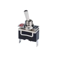


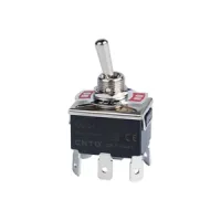
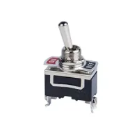


| Part Number: | C5R | 11 | B |
|---|---|---|---|
| Explanation: |
Type CO - Maintained action, 10A at 250VAC |
Contact 11 - Single-pole single-throw, ON-OFF |
Terminal A - #250 tab terminal |
C5 toggle switches provide maintained or spring-return switching in single- and double-pole configurations. Choose ON-OFF, ON-ON or center-off ON-OFF-ON contacts, then select tab, screw or solder terminals. The mounting hole is Ø12mm; optional protective caps provide water and oil protection.
| Field | Code | Selection |
|---|---|---|
| Type | CO | Maintained action; 10A at 250VAC |
| COR | Spring return; 10A at 250VAC | |
| C5 | Maintained action; 15A at 250VAC | |
| C5R | Spring return; 15A at 250VAC | |
| Contact | 11 | Single-pole single-throw, ON-OFF |
| 12 | Single-pole double-throw, ON-ON | |
| 13 | Single-pole double-throw, center-off ON-OFF-ON | |
| 131 | Single-pole double-throw, center OFF with single-side return | |
| 21 | Double-pole single-throw, ON-OFF | |
| 22 | Double-pole double-throw, ON-ON | |
| 23 | Double-pole double-throw, center-off ON-OFF-ON | |
| 231 | Double-pole double-throw, center OFF with single-side return | |
| Terminal | A | #250 tab terminal |
| B | Screw terminal | |
| C | #187 solder terminal |
The complete example C5R11B selects a 15A-at-250VAC spring-return SPST switch with screw terminals. Contact codes 131 and 231 require a spring-return type. Specify the required returning side for a single-side-return configuration.

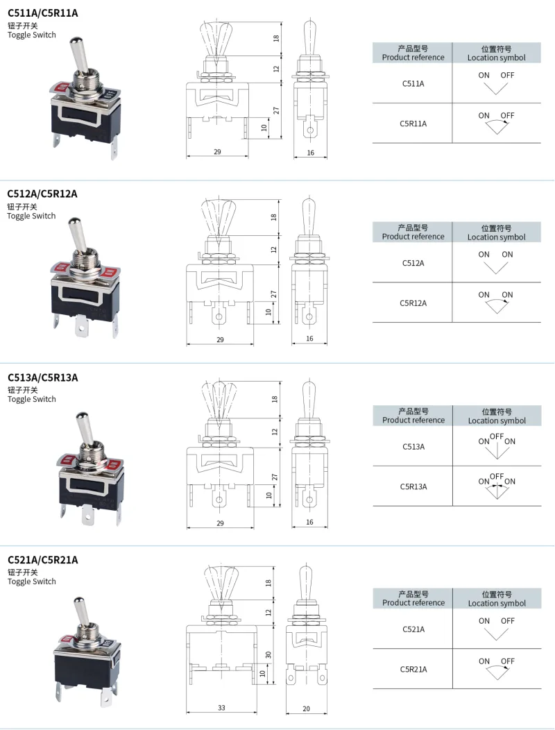
Maintained models hold the selected position. Spring-return 11/21 models return to OFF; 12/22 models return from one ON position to the other ON position. Spring-return 13/23 models return from either ON position to center OFF.
| Terminal | Contact form | Switching function | Maintained model | Spring-return model |
|---|---|---|---|---|
| A: #250 tab | SPST | ON-OFF | C511A | C5R11A |
| SPDT | ON-ON | C512A | C5R12A | |
| ON-OFF-ON | C513A | C5R13A | ||
| DPST | ON-OFF | C521A | C5R21A | |
| DPDT | ON-ON | C522A | C5R22A | |
| ON-OFF-ON | C523A | C5R23A | ||
| B: screw | SPST | ON-OFF | C511B | C5R11B |
| SPDT | ON-ON | C512B | C5R12B | |
| ON-OFF-ON | C513B | C5R13B | ||
| DPST | ON-OFF | C521B | C5R21B | |
| DPDT | ON-ON | C522B | C5R22B | |
| ON-OFF-ON | C523B | C5R23B |
| Parameter | Value |
|---|---|
| Initial contact resistance | ≤15mΩ |
| Insulation resistance | ≥100MΩ at 500VDC |
| Dielectric strength | 2000VAC, 50/60Hz for 1 minute |
| Vibration | 10–55Hz, 1.5mm double amplitude |
| Operating temperature | −20°C to +70°C, no icing |
| Humidity | ≤85%RH |
| Electrical life | ≥500000 operations; load conditions not specified |
Choose ratings for the load type and voltage. CO and C5 identify the two current families in the table. A voltage reference without current or power does not define a complete load rating.
| Load | Type | AC rating | DC rating |
|---|---|---|---|
| Resistive | CO | 10A at 250V; 15A at 125V | 0.4A at 250V; 0.8A at 125V |
| C5 | 15A at 250V; 20A at 125V | 0.5A at 250V; 0.9A at 125V | |
| Inductive | CO | 10A at 250V; 15A at 125V | 0.2A at 250V; 0.4A at 125V |
| C5 | 15A at 250V; 20A at 125V | 0.3A at 250V; 0.5A at 125V | |
| Lamp | CO | 300W at 100V; 500W at 200V | 30V reference; allowable current/power not specified |
| C5 | 400W at 125V; 800W at 250V | Not specified | |
| Motor | CO | 200W at 125V; 300W at 250V | 7A at 30V |
| C5 | 400W at 125V, single phase | Not specified | |
| CO | 550W at 250V, three phase | Not specified | |
| C5 | 750W at 250V, three phase |
| Terminal code | Connection | Dimensions |
|---|---|---|
| A | #250 tab | 6.35±0.1mm wide, 0.8mm thick; Ø1.6mm hole |
| B | Screw | M3.5×0.6 |
| C | #187 solder | 4.75±0.1mm wide, 0.5mm thick; Ø1.6mm hole |

| Model group | Illustrated footprint | Rear height including terminal extent | Terminal extent | Bushing height | Lever length above bushing |
|---|---|---|---|---|---|
| C511/C512/C513 and C5R11/C5R12/C5R13, A/B terminals | 29×16mm | 27mm | 10mm | 12mm | 18mm |
| C521/C522/C523 and C5R21/C5R22/C5R23, A/B terminals | 33×20mm | 30mm |


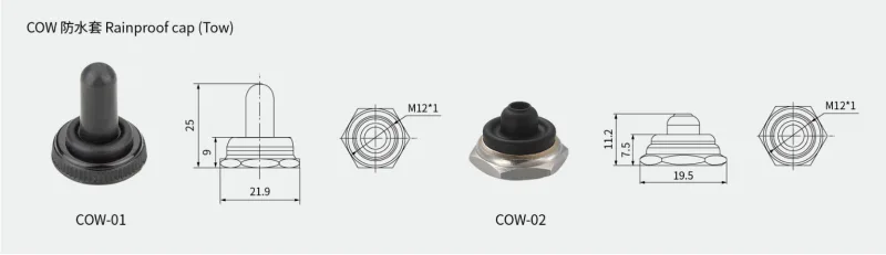
| Accessory | Thread | Width | Overall height | Base height reference |
|---|---|---|---|---|
| COW-01 | M12×1 | 21.9mm | 25mm | 9mm |
| COW-02 | 19.5mm | 11.2mm | 7.5mm |
These switches are intended for industrial use. High-reliability infrastructure, applications involving personal safety, harsh outdoor or contaminated conditions, fire or explosion hazards, military uses and aerospace projects require a specifically designed and expressly confirmed configuration.
