

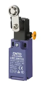


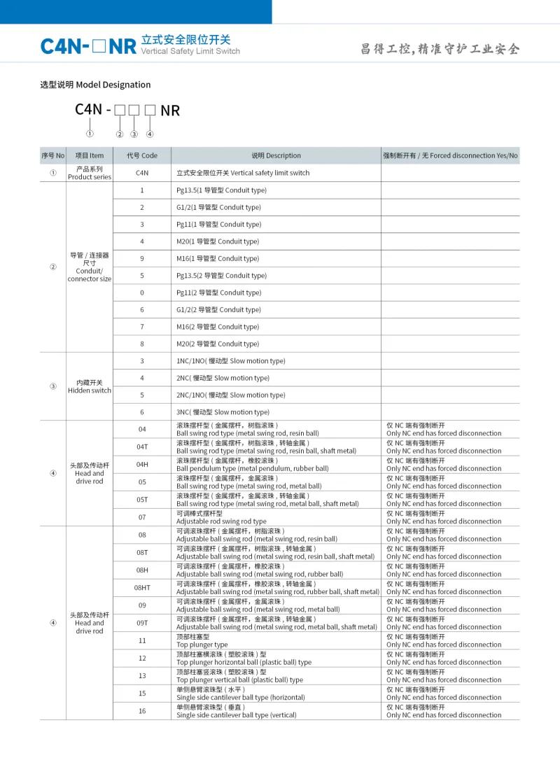
| Part Number: | C4N | - | 4 | 3 | 04 | NR |
|---|---|---|---|---|---|---|
| Explanation: |
Series C4N - Vertical limit switch series |
Conduit 1 - Pg13.5, single entry |
Contact 3 - 1NC+1NO, slow action |
Actuator 04 - Metal lever with resin roller |
Reset NR - Manual-reset version; direct opening applies to NC contacts only |
C4N-NR vertical limit switches combine a manual reset mechanism, slow-action contacts and an IP67 enclosure. Eleven M20 single-entry configurations cover roller levers, an adjustable rod, plungers and cantilever rollers. The reset button restores the switch after actuation; keep the actuator securely fastened and reset it manually after use. Direct opening applies to the NC contacts only.
All models below use contact code 3: 1NC+1NO, slow action. Body width is 31mm maximum and depth is 30mm. Dimensions below identify the working head; use the attachment drawings for the complete mounting envelope.
| Model | Actuator | Working dimensions |
|---|---|---|
| C4N-4304NR | Metal lever with resin roller | Roller Ø18×6.5mm; radius 26mm |
| C4N-4304HNR | Metal lever with rubber roller | Roller Ø50×8mm |
| C4N-4305NR | Metal lever with metal roller | Roller Ø18×6.5mm; radius 26mm |
| C4N-4307NR | Adjustable metal rod | Rod Ø2.5×128mm |
| C4N-4308NR | Adjustable metal lever with resin roller | Roller Ø18×6.5mm; radius 22–66mm |
| C4N-4308HNR | Adjustable metal lever with rubber roller | Roller Ø50×8mm; radius 30–66mm |
| C4N-4311NR | Resin top plunger | Plunger Ø6mm; head height 35.5mm |
| C4N-4312NR | Horizontal resin roller plunger | Roller Ø9×5mm; head height 46mm |
| C4N-4313NR | Vertical resin roller plunger | |
| C4N-4315NR | Horizontal cantilever resin roller | Roller Ø9×5mm; head height 51mm |
| C4N-4316NR | Vertical cantilever resin roller | Roller Ø22.5×5mm; head height 66.2mm |
The ordering sequence is C4N, a hyphen, conduit code, contact code, complete actuator code and NR. For example, C4N-4304NR identifies an M20 single-entry switch with slow-action 1NC+1NO contacts and a resin roller lever. NR identifies the manual-reset version. The following alternatives are ordering options; their presence does not establish stock availability for every combination.
| Conduit configuration | Code | Thread |
|---|---|---|
| Single entry | 1 | Pg13.5 |
| 2 | G1/2 | |
| 3 | Pg11 | |
| 4 | M20 | |
| 9 | M16 | |
| Two entries | 5 | Pg13.5 |
| 0 | Pg11 | |
| 6 | G1/2 | |
| 7 | M16 | |
| 8 | M20 |
| Actuator code | Head and drive arrangement | Direct opening |
|---|---|---|
| 04 | Metal lever, resin roller | NC contacts only |
| 04T | Metal lever, resin roller, metal shaft | |
| 04H | Metal lever, rubber roller | |
| 05 | Metal lever, metal roller | |
| 05T | Metal lever, metal roller, metal shaft | |
| 07 | Adjustable metal rod | |
| 08 | Adjustable metal lever, resin roller | |
| 08T | Adjustable metal lever, resin roller, metal shaft | |
| 08H | Adjustable metal lever, rubber roller | |
| 08HT | Adjustable metal lever, rubber roller, metal shaft | |
| 09 | Adjustable metal lever, metal roller | |
| 09T | Adjustable metal lever, metal roller, metal shaft | |
| 11 | Top plunger | |
| 12 | Horizontal resin roller plunger | |
| 13 | Vertical resin roller plunger | |
| 15 | Horizontal cantilever roller | |
| 16 | Vertical cantilever roller |
| Contact code | Slow-action arrangement | NC terminals with direct opening | NO terminals |
|---|---|---|---|
| 3 | 1NC+1NO | 11–12 | 33–34 |
| 4 | 2NC | 11–12 and 31–32 | — |
| 5 | 2NC+1NO | 11–12 and 21–22 | 33–34 |
| 6 | 3NC | 11–12, 21–22 and 31–32 | — |
The separate contact circuits may carry different polarities. In 1NC+1NO and 2NC+1NO versions, NC opening precedes NO closing. Multiple NC contacts need not change state at exactly the same actuator position. Direct opening is a contact function and does not specify a complete machine safety performance level.
| Parameter | Value and condition |
|---|---|
| Enclosure protection | IP67; verify sealing in the installed environment |
| Electric shock protection | Class II, double insulation |
| Rated insulation voltage Ui | 500V |
| Conventional free-air thermal current Ith | 10A |
| Electrical operating frequency | 30 operations/min |
| Operating speed reference | 1mm/s–0.5m/s, designated reference C4N-104R; actuator-specific applicability must be checked |
| Initial contact resistance | 25mΩ maximum |
| Insulation resistance | 100MΩ minimum at 500VDC |
| Minimum applicable load | 24VDC, 10mA |
| Slow-action contact gap | 2×2mm minimum |
| Pollution degree | 3, EN60947-5-1 |
| Vibration, malfunction resistance | 10–55Hz, 0.75mm single amplitude |
| Shock, mechanical durability | 1,000m/s² |
| Shock, malfunction resistance | 300m/s² |
| Operating temperature | -20°C to +70°C, no icing |
| Ambient humidity | Below 95%RH |
| Electrical endurance | Resistive test load | Ambient test conditions |
|---|---|---|
| More than 500,000 operations | 250VAC, 3A | 5–35°C; 40–70%RH |
| More than 300,000 operations | 250VAC, 10A |
These initial and endurance characteristics depend on load, switching frequency and environment. Do not simultaneously switch two or more 250VAC, 3A standard-load circuits; the restriction also applies above 35°C. Thermal current and resistive endurance test loads are separate from utilization-category ratings.
| Dielectric test location | Withstand voltage |
|---|---|
| Between same-polarity terminals | 2.5kV |
| Between different-polarity terminals | 4kV |
| Between terminals and non-live metal parts | 6kV |
| Rating category | Current | Voltage | Load or standard |
|---|---|---|---|
| AC-15 | 3A | 250V | EN60947-5-1 / GB/T14048.5 |
| DC-13 | 0.3A | 220V | |
| CSA rating entries | 3A | 240V | Resistive; C22.2 No.14 |
| 0.27A | 250V |
Provide external short-circuit protection using a 10A gI or gG fuse complying with IEC60269; no fuse is built into the switch.
| Declared conformity reference | Associated standard |
|---|---|
| CCC | GB/T14048.5 |
| TUV | EN60947-5-1 |
| CE |
Obtain documentation applicable to the selected configuration when a project requires certification evidence.
This table applies to actuator codes 04, 04H, 05, 07, 08, 08H and 09. The listed C4N-43…NR models use the 1NC+1NO column. The 2NC and 3NC values describe alternative contact configurations. Adjustable-lever measurements use a 35mm setting. TT is a reference value.
| Parameter | 2NC / 3NC, codes 4 / 6 | 1NC+1NO / 2NC+1NO, codes 3 / 5 |
|---|---|---|
| Locking force LF | 8N | |
| Locking travel LT | 50±5° | |
| NC opening pretravel PT1 | 25±5° | |
| NO closing pretravel PT2 | Not applicable | 40±5° |
| Overtravel OT, maximum | 50° | 35° |
| Total travel TT, reference | 80° | |
| Direct opening travel DOT, minimum | 35° | |
| Direct opening force DOF, minimum | 20N | |
Values apply to slow-action 1NC+1NO, 2NC, 2NC+1NO and 3NC configurations. PT2 concerns NO-equipped versions only. Measurements use vertical force for plungers and actuator 15, and horizontal force for actuator 16. TT values are references.
| Parameter | C4N-4311NR / C4N-4312NR / C4N-4313NR | C4N-4315NR | C4N-4316NR |
|---|---|---|---|
| Locking force LF | 15N | 10N | |
| Locking travel LT | 3.5±0.3mm | 4.7±0.5mm | 6±0.5mm |
| NC opening pretravel PT1 | 1.7±0.3mm | 2.2±0.5mm | 3±0.5mm |
| NO closing pretravel PT2 | 2.5±0.3mm | 3.2±0.5mm | 4±0.5mm |
| Overtravel OT, maximum | 3.2mm | 4.3mm | 5.5mm |
| Total travel TT, reference | 6mm | 8mm | 10mm |
| Direct opening travel DOT, minimum | 2.5mm | 3.2mm | 4.5mm |
| Direct opening force DOF, minimum | 20N | ||
Mount with M4 screws and spring washers. The optional additional locating studs have nominal 4mm diameter and a height no greater than 4.8mm. The head can be installed in four orientations after removing its four screws; keep foreign material out during adjustment. Roller levers can be set around 360° in 7.5° increments. Secure the grooved lever-to-shaft joint and stay within the specified operating travel.
| Position | Fastener or fitting | Tightening torque |
|---|---|---|
| 1 | Terminal screw | 0.5–0.7N·m |
| 2 | Cover screw | 0.5–0.6N·m |
| 3 | Head mounting screw | 1.6–1.8N·m |
| 4 | Lever mounting screw | 0.5–0.7N·m |
| 5 | Body mounting screw | 1.8–2.2N·m |
| 6 | Connector / M12 adapter | 1.3–1.7N·m |
| 7 | Conduit cap |
Isolate power before wiring. Use AWG20–AWG18 or 0.5–0.75mm² conductors with insulated M3.5 crimp terminals, maximum terminal thickness 0.5mm. Keep wire fragments out and arrange conductors so the cover closes without pinching. Match the cable diameter to its connector and close unused openings on two-entry bodies.
| Crimp-terminal dimension | Value |
|---|---|
| t | 0.5mm |
| Ødz | 3.7mm |
| ØD | 2.9mm |
| B | 6.6mm |
| L | 19mm |
| F | 7.7mm |
| l | 8.0mm |
| Three-contact body wiring arrangement | Terminal positions | Prepared conductor length |
|---|---|---|
| Single entry | A, B | 42±2mm |
| C, D | 33±2mm | |
| E, F | 28±2mm | |
| Two entries, left-side cable | A, C, E | 42±2mm |
| B, D, F | 28±2mm | |
| Two entries, right-side cable | A, C, E | 28±2mm |
| B, D, F | 42±2mm |
The A–F positions and terminal geometry refer to the three-contact wiring drawings in the attachment; they do not add a third contact to the listed 1NC+1NO models.
Use indoors and protect the switch from oil, rainwater, seawater, standing water and prolonged immersion. Close the cover before energizing. Contacts previously used with a standard load should not be reassigned to a smaller load. Standard contacts require at least 24VDC and 10mA; lower loads require a separately selected contact specification. Use appropriate suppression for inductive transients.
Application-specific engineering is required for personnel protection, high-reliability continuous systems, severe chemical or electromagnetic exposure, explosive atmospheres, nuclear, aerospace or military service. The component data alone do not establish suitability for those applications.
