


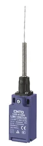
| Part Number: | C4N | - | 4 | 1 | 11 | N |
|---|---|---|---|---|---|---|
| Explanation: |
Series C4N - Vertical limit switch series |
Conduit 1 - Pg13.5, single entry |
Contact 1 - 1NC/1NO, snap action |
Actuator 11 - Resin top plunger |
Version N - Fixed suffix for this C4N-N version |
C4N-N limit switches offer plunger, cantilever roller, rotary lever and flexible spring heads in an IP67 enclosure. Select the actuator for the direction of approach, then specify conduit size and contact action. Rigid heads provide direct opening of fitted NC contacts; flexible heads 66, 67, 68 and 69 do not provide direct opening. NO contacts have no direct-opening function.
Snap-action, slow-action and make-before-break contacts have different travel characteristics. MBB closes the NO contact before opening the NC contact. A component's direct-opening mechanism does not establish the performance level of a complete machine safety circuit.
The example C4N-4111N combines the C4N family, a hyphen, conduit code 4, contact code 1, complete actuator code 11 and fixed suffix N: M20 single entry, snap-action 1NC/1NO and resin top plunger.
| Entry arrangement | Pg13.5 | G1/2 | Pg11 | M20 | M16 |
|---|---|---|---|---|---|
| Single entry code | 1 | 2 | 3 | 4 | 9 |
| Two entry code | 5 | 6 | 0 | 8 | 7 |
| Contact code | Contact action | NC terminals | NO terminals |
|---|---|---|---|
| 1 | 1NC/1NO, snap | 31–32 | 13–14 |
| 3 | 1NC/1NO, slow | 11–12 | 33–34 |
| 4 | 2NC, slow | 11–12 and 31–32 | None |
| 7 | 1NC/1NO, slow MBB | 11–12 | 33–34 |
| 9 | 2NO, slow | None | 13–14 and 33–34 |
Terminal numbering follows EN 50013 and contact forms refer to EN 60947-5-1. Separate contact poles may use different polarities within the rated insulation limits. Contact switching points need not be simultaneous on multi-contact blocks.
| Actuator code | Construction | Direct opening |
|---|---|---|
| 11 / 21 | Resin / metal top plunger | Fitted NC contacts only |
| 22 / 23 | Horizontal / vertical metal roller plunger | |
| 32 / 33 | Horizontal / vertical roller plunger with metal head | |
| 15 / 16 | Horizontal / vertical cantilever roller | |
| 04 / 04T | Metal lever, resin roller; T adds a metal shaft | |
| 05 / 05T | Metal lever, metal roller; T adds a metal shaft | |
| 04H | Metal lever, rubber roller | |
| 07 | Adjustable metal rod | |
| 08 / 08T | Adjustable resin roller lever; T adds a metal shaft | |
| 09 / 09T | Adjustable metal roller lever; T adds a metal shaft | |
| 08H / 08HT | Adjustable rubber roller lever; HT has a metal shaft | |
| 66 | Plastic rod | Unavailable |
| 67 | Coil spring | |
| 68 | Metal rod with coil spring | |
| 69 | Flexible whisker |

| Parameter | Value or condition |
|---|---|
| Rated load AC-15 | 3A at 250VAC |
| Rated load DC-13 | 0.3A at 220VDC |
| Rated insulation voltage Ui | 500V |
| Conventional thermal current Ith | 10A |
| Electrical endurance | More than 500,000 cycles at 250VAC, 3A resistive; 5–35°C and 40–70%RH |
| Electrical operating frequency | 30 operations/min |
| Operating speed reference | 1mm/s–0.5m/s, specified with legacy test reference C4N-4103; assess the selected head and cam separately |
| Initial contact resistance | 25mΩ maximum |
| Insulation resistance | 100MΩ minimum at 500VDC |
| Minimum standard-contact load | 24VDC, 10mA |
| Dielectric withstand, same-pole terminals | 2.5kV |
| Dielectric withstand, different-pole terminals | 4kV |
| Dielectric withstand, terminals to non-live metal | 6kV |
| Contact gap | Snap: at least 2×0.5mm; slow: at least 2×2mm |
| Vibration, malfunction resistance | 10–55Hz, 0.75mm single amplitude |
| Shock resistance | Durability: 1000m/s²; malfunction: 300m/s² |
| Temperature | -20°C to +70°C, without icing |
| Humidity | Below 95%RH |
| Protection | IP67; Class II double insulation; pollution degree 3 under EN 60947-5-1 |
Use a suitable IEC 60269 gI/gG 10A fuse for the specified short-circuit protection arrangement; the switch contains no fuse. Avoid simultaneously switching two or more 3A, 250VAC standard-load circuits, particularly above 35°C. Keep the closed enclosure and cable entries sealed. IP67 does not make prolonged submersion, oil exposure or chemical contamination suitable operating conditions.
| Specification reference | Standard or rating |
|---|---|
| CCC | GB/T 14048.5 |
| TUV and CE | EN 60947-5-1 |
| CSA reference | C22.2 No.14; resistive ratings shown as 3A at 240V and 0.27A at 250V |
Model-specific certification documents determine applicability; the specification references above are not a declaration that every ordering combination has every approval.
OF is maximum operating force; RF is minimum release force; PT is pretravel; MD is movement differential; OT is maximum overtravel; TT is reference total travel; OP is operating position. DOT and DOF are minimum direct-opening travel and force and apply only to eligible NC contacts. Measure the following plungers in the vertical force direction.
| Characteristic | Snap contacts | Slow 2NC/2NO group | Slow 1NC/1NO | MBB 1NC/1NO |
|---|---|---|---|---|
| Actuator codes | 11, 21, 22, 23, 32, 33 | |||
| OF | 10N | 15N | ||
| RF | 1.5N | |||
| PT / NC opening PT1 | 1.7±0.3mm | 2.2±0.3mm | ||
| NO closing PT2 | Not separately specified | 2.5±0.3mm | 1±0.3mm | |
| MD, snap only | 0.8±0.2mm | Not specified | ||
| OT maximum | 4mm | 3.2mm | 3.5mm | |
| TT reference | 6mm | |||
| DOT minimum | 3.5mm | 2.5mm | 3mm | |
| DOF minimum | 20N; no direct opening on 2NO contacts | |||
| Actuator | OP for snap / slow 2NC/2NO group | Slow/MBB OP at NO closing | Slow/MBB OP at NC opening |
|---|---|---|---|
| 11 | 17.5±0.5mm | 16.7±0.5mm | 17±0.5mm |
| 21 | 27±0.5mm | 26.2±0.5mm | 26.5±0.5mm |
| 22 / 23 | 29±0.5mm | 28.2±0.5mm | 28.5±0.5mm |
| 32 / 33 | 30.8±0.5mm | 30±0.5mm | 30.3±0.5mm |
Head 15 has a horizontal roller and is measured with vertical force. Head 16 has a vertical roller and is measured with horizontal force. The values below are paired as head 15 / head 16.
| Characteristic | Snap contacts | Slow 2NC/2NO group | Slow 1NC/1NO | MBB 1NC/1NO |
|---|---|---|---|---|
| OF | 8N / 8N | 10N / 10N | ||
| RF | 1.5N / 1.5N | |||
| PT / NC opening PT1 | 2.2±0.5mm / 3±0.5mm | 2.8±0.5mm / 3.5±0.5mm | ||
| NO closing PT2 | Not separately specified | 3.2±0.5mm / 4.2±0.5mm | 1.2±0.5mm / 1.7±0.5mm | |
| MD, snap only | 1.3±0.3mm / 1±0.3mm | Not specified | ||
| OT maximum | 5.3mm / 6.5mm | 4.3mm / 5.5mm | 4.7mm / 5.7mm | |
| TT reference | 8mm / 10mm | |||
| OP, snap / slow 2NC/2NO group | 32.3±0.5mm / 51.5±0.5mm | See separate switching points below | ||
| OP at NO closing, slow/MBB | Not separately specified | 31.3±0.8mm / 52±0.8mm | ||
| OP at NC opening, slow/MBB | Not separately specified | 31.7±0.8mm / 51.7±0.8mm | ||
| DOT minimum | 5.5mm / 6mm | 3.2mm / 4.5mm | 4mm / 5.5mm | |
| DOF minimum | 20N; eligible NC contacts only | |||
The rotary data apply to illustrated heads 04, 04H, 05, 07, 08, 08H and 09. Adjustable-head measurements use a 35mm lever setting. Match the complete metal-shaft option to the relevant dimensional drawing before ordering.
| Characteristic | Snap contacts | Slow 2NC/2NO group | Slow 1NC/1NO | MBB 1NC/1NO |
|---|---|---|---|---|
| OF / RF | 8N maximum / 0.5N minimum | |||
| PT / NC opening PT1 | 25±5° | 35±5° | ||
| NO closing PT2 | Not separately specified | 40±5° | 15±5° | |
| MD, snap only | 12±2° | Not specified | ||
| OT maximum | 50° | 35° | 40° | |
| TT reference | 80° | |||
| OP | Not specified | |||
| DOT minimum | 50° | 35° | 40° | |
| DOF minimum | 20N; eligible NC contacts only | |||
| Characteristic | Flexible heads 66, 67, 68, 69 |
|---|---|
| OF maximum | 3N |
| RF minimum | 0.5N |
| PT | 10±5° |
| Measurement condition | Force applied at two-thirds of the unbent head spring length |
| OT, TT, OP and MD | Not specified |
| Direct opening | Unavailable |
The attachment also shows 3NC and 2NC/1NO mechanical and wiring arrangements. These are additional configurations, not an assurance that every head and conduit combination accepts every contact block. Their switching points may differ between contacts; obtain the exact configuration drawing.
The single-entry body drawing has a 55mm reference height, 31mm maximum width and 30mm depth. Fix the body with M4 screws and spring washers. Mounting drawings show 20/22±0.1mm horizontal alternatives and 47±0.1mm vertical spacing for single-entry bodies; two-entry drawings show 20/22/40/42±0.1mm alternatives and 39±0.1mm vertical spacing. Optional lower locating pins are Ø4mm with -0.05/-0.15mm tolerance and at most 4.8mm high. Use the complete attachment drawings to choose the matching holes.
| Fastener | Tightening torque |
|---|---|
| Terminal screw | 0.49–0.59N·m |
| Outer cover | 0.5–0.6N·m |
| Head | 0.35–0.45N·m |
| Lever or rod | 1.2–1.3N·m |
| Body | 0.5–0.7N·m |
| Connector or applicable M12 adapter | 1.8–2.2N·m |
| Conduit closure cap | 1.3–1.7N·m |
The head can be repositioned in four directions; roller-plunger orientation has two positions 90° apart. Lever position can be set in 7.5° steps around 360°. Engage the shaft and lever grooves fully before tightening. Adjustable levers also permit length setting. For reversed lever mounting, follow the front-screw procedure in the drawing and keep the indicated movement within 180°.
Use a separate mechanical stop and align the cam with the intended actuator force direction. The attachment includes EN 50047 cam approach, clearance and position diagrams for each head; these geometries differ between fixed rollers, adjustable rollers, plungers and cantilever heads. Avoid diagonal loading that can bend the lever or shaft. Keep the rod locked, the cover closed and foreign matter away from the mechanism.
| Additional contact code in installation diagrams | Arrangement | Terminals |
|---|---|---|
| 2 | 2NC snap | 11–12 and 31–32 |
| 5 / 8 | 2NC/1NO slow / slow MBB | NC 11–12, 21–22; NO 33–34 |
| 6 | 3NC | 11–12, 21–22 and 31–32 |
These additional arrangements are absent from the main ordering chart and require matching configuration availability. No M12 connector version is specified for the three-contact switches.
Disconnect power before wiring. Use insulated M3.5 crimp terminals and 0.5–0.75mm² conductors, approximately AWG20–AWG18. Position terminals to avoid the housing and cover, remove loose wire fragments and ensure the cover closes freely.
| Crimp terminal dimension | Value |
|---|---|
| Thickness | 0.5mm maximum |
| Stud hole / barrel diameter | 3.7mm / 2.9mm |
| Width B / length L | 6.6mm / 19mm |
| F / l | 7.7mm / 8mm |
| Cable | Cores | Conductor | Overall diameter |
|---|---|---|---|
| Plastic or rubber insulated flexible | 2, 3 or 4 | 0.5–0.75mm² | Circular, Ø6–9mm |
| 600V plastic insulated, plastic sheathed VVF | 2 | Ø1mm, Ø1.2mm or Ø1.6mm |
| Three-contact wiring reference | Conductor lengths |
|---|---|
| Single entry | A/B: 42mm; C/D: 33mm; E/F: 28mm; tolerance ±2mm |
| Two entries, left-side approach | E/C/A: 42mm; B/D/F: 28mm; tolerance ±2mm |
| Two entries, right-side approach | B/D/F: 42mm; E/C/A: 28mm; tolerance ±2mm |
The letter positions refer to the attachment's three-contact diagram. Match the cable gland to both entry thread and cable diameter. Cap and tighten unused entries on two-entry bodies. Avoid silicone-containing wiring materials because contamination can impair contact reliability.
Below 24VDC and 10mA, standard-contact current may not break through surface films. Choose a contact design specified for the actual signal load. Do not reuse contacts previously operated at general loads for smaller-capacity signals. Use suitable suppression where inrush, arcing or electrical noise would reduce contact endurance.
Applications requiring exceptional reliability, personal safety protection, hazardous-atmosphere operation, severe environmental exposure, aerospace or military use require an expressly assessed configuration and complete system design. Verify the selected model, contact action, cam path and electrical duty together before installation.
