


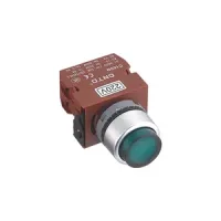


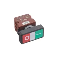
The C2/C3 range combines metal operators with removable brown contact blocks and a direct insertion connection between the head and mounting body. The detailed C2 selections cover flat and raised pushbuttons, 40mm and 60mm mushroom heads, illuminated operators, selectors, key controls, two-direction and four-direction joysticks, and red/green twin buttons. C2 uses a 22mm panel opening; C3 denotes the 30mm opening in the family guide. The full models and dimensions below are the listed C2 configurations.
Choose the operating action, contact arrangement and lamp supply together. Most red pushbutton selections use 1B, one normally closed contact, while the other listed colors use 1A, one normally open contact. Maintained pushbuttons have a -D suffix before the contact slash. Selector and joystick codes use F for maintained operation and T for spring return. These are control circuit components; select the actual contact block and switching duty rather than treating the 10A thermal rating as the usable current at every load.

| Field | Codes and meaning | Selection condition |
|---|---|---|
| Panel opening | C2: 22mm; C3: 30mm | The detailed model tables and dimension drawings in this page describe C2. |
| Pushbutton heads | PNF: flat; PNH: raised; PNM3/PNM4/PNM6: 30mm/40mm/60mm mushroom; PNR3/PNR4/PNR6: 30mm/40mm/60mm emergency-stop type; PNKM4: keyed emergency-stop type; PND: twin button; PNP: pull/stretch operator | PNM3, PNR3 and PNP are general guide options without a full selection table here. The emergency-stop head group does not use the pushbutton -D option. |
| Illuminated and other heads | PIF: flat illuminated; PIH: raised illuminated; PIM4: 40mm illuminated mushroom; PID: illuminated twin; SIS: short illuminated selector; SIL: long illuminated selector; LIF: standard indicator; LUF: circular indicator; MN: joystick | LIF and LUF are family guide options. An illuminated model requires the specified lamp supply. |
| Selector heads | SNS: short handle; SNL: long handle; SNK: key selector | Use the listed action/contact combinations rather than combining every option freely. |
| Pushbutton action | No action suffix: momentary; D: maintained | The actual maintained model is written C2PNF-D/1B-R, for example; there is no hyphen between C2 and PNF. |
| Selector/joystick action | F2/F3/F4: maintained, two/three/four positions or directions; T2/T3/T4: spring return, two/three/four positions or directions | F4/T4 are listed for the joystick. The selector tables use F2/T2/F3/T3. |
| Contact codes | 1A: 1NO; 1B: 1NC; 1C: 1NO1NC; 1D: 1NO+1NC; 1F: 1NO+1NO; 1G: 1NC+1NC; 2A: 2NO; 2B: 2NC; 2C: 1NO1NC+1NO1NC; 2D: 2NO+2NC; 2G: 2NC+2NC | The guide retains distinct codes for different block combinations with the same total contact count. Only the contacts listed against a particular operator are specified selections. |
| Color | R: red; G: green; Y: yellow; W: white; B: black; S: blue | Black is absent from the illuminated pushbutton tables. The R4/R6 tables list red, green, yellow and black. Twin buttons have fixed red/green faces without a color suffix. |
| Lamp supply, △ | 12: 12VDC; 24: 24VDC; 36: 36VDC; 48: 48VDC; 110: 110VAC; 220: 220VAC; 380: 380VAC | Replace △ with one supply code. The low-voltage codes are DC and the 110/220/380 codes are AC; do not assume interchangeable AC/DC operation. |
Each model below is listed with its contact and color combination. A lamp triangle marks a supply code to be selected from the seven choices above.
| Operator and action | Red, 1NC | Other listed models, 1NO |
|---|---|---|
| Flat, momentary | C2PNF/1B-R | C2PNF/1A-G C2PNF/1A-Y C2PNF/1A-W C2PNF/1A-B C2PNF/1A-S |
| Flat, maintained | C2PNF-D/1B-R | C2PNF-D/1A-G C2PNF-D/1A-Y C2PNF-D/1A-W C2PNF-D/1A-B C2PNF-D/1A-S |
| Flat illuminated, momentary | C2PIF/1B-R-△ | C2PIF/1A-G-△ C2PIF/1A-Y-△ C2PIF/1A-W-△ C2PIF/1A-S-△ |
| Flat illuminated, maintained | C2PIF-D/1B-R-△ | C2PIF-D/1A-G-△ C2PIF-D/1A-Y-△ C2PIF-D/1A-W-△ C2PIF-D/1A-S-△ |
| Raised, momentary | C2PNH/1B-R | C2PNH/1A-G C2PNH/1A-Y C2PNH/1A-W C2PNH/1A-B C2PNH/1A-S |
| Raised, maintained | C2PNH-D/1B-R | C2PNH-D/1A-G C2PNH-D/1A-Y C2PNH-D/1A-W C2PNH-D/1A-B C2PNH-D/1A-S |
| Raised illuminated, momentary | C2PIH/1B-R-△ | C2PIH/1A-G-△ C2PIH/1A-Y-△ C2PIH/1A-W-△ C2PIH/1A-S-△ |
| Raised illuminated, maintained | C2PIH-D/1B-R-△ | C2PIH-D/1A-G-△ C2PIH-D/1A-Y-△ C2PIH-D/1A-W-△ C2PIH-D/1A-S-△ |
| 40mm mushroom, momentary | C2PNM4/1B-R | C2PNM4/1A-G C2PNM4/1A-Y C2PNM4/1A-W C2PNM4/1A-B C2PNM4/1A-S |
| 40mm mushroom, maintained | C2PNM4-D/1B-R | C2PNM4-D/1A-G C2PNM4-D/1A-Y C2PNM4-D/1A-W C2PNM4-D/1A-B C2PNM4-D/1A-S |
| 40mm illuminated mushroom, momentary | C2PIM4/1B-R-△ | C2PIM4/1A-G-△ C2PIM4/1A-Y-△ C2PIM4/1A-W-△ C2PIM4/1A-S-△ |
| 40mm illuminated mushroom, maintained | C2PIM4-D/1B-R-△ | C2PIM4-D/1A-G-△ C2PIM4-D/1A-Y-△ C2PIM4-D/1A-W-△ C2PIM4-D/1A-S-△ |
| 60mm mushroom, momentary | C2PNM6/1B-R | C2PNM6/1A-G C2PNM6/1A-Y C2PNM6/1A-W C2PNM6/1A-B C2PNM6/1A-S |
| 60mm mushroom, maintained | C2PNM6-D/1B-R | C2PNM6-D/1A-G C2PNM6-D/1A-Y C2PNM6-D/1A-W C2PNM6-D/1A-B C2PNM6-D/1A-S |
| 40mm emergency-stop type | C2PNR4/1B-R | C2PNR4/1A-G C2PNR4/1A-Y C2PNR4/1A-B |
| 60mm emergency-stop type | C2PNR6/1B-R | C2PNR6/1A-G C2PNR6/1A-Y C2PNR6/1A-B |
| Operator | Two-position maintained, 1NO | Two-position spring return, 1NO | Three-position maintained, 1NO+1NO | Three-position spring return, 1NO+1NO |
|---|---|---|---|---|
| 40mm keyed emergency-stop type | C2PNKM4-F2/1A | C2PNKM4-T2/1A | C2PNKM4-F3/1F | C2PNKM4-T3/1F |
| Short handle | C2SNS-F2/1A | C2SNS-T2/1A | C2SNS-F3/1F | C2SNS-T3/1F |
| Illuminated short handle | C2SIS-F2/1A-△ | C2SIS-T2/1A-△ | C2SIS-F3/1F-△ | C2SIS-T3/1F-△ |
| Long handle | C2SNL-F2/1A | C2SNL-T2/1A | C2SNL-F3/1F | C2SNL-T3/1F |
| Illuminated long handle | C2SIL-F2/1A-△ | C2SIL-T2/1A-△ | C2SIL-F3/1F-△ | C2SIL-T3/1F-△ |
| Key selector | C2SNK-F2/1A | C2SNK-T2/1A | C2SNK-F3/1F | C2SNK-T3/1F |
The illuminated selector color choices are green, red, yellow and blue; their printed model patterns do not add a color suffix, so specify the lens color with the order. The PNKM4 key-position drawings show withdrawal at both maintained F2 positions, the rest position on T2, all three F3 positions, and the center rest position on T3. No separate key-withdrawal schedule is specified for SNK. The keyed emergency-stop type selections above are NO-contact models; the head name alone does not specify an NC safety circuit or a safety rating.
| Operator | Full selections | Contacts or color |
|---|---|---|
| Two-direction joystick, spring return | C2MN-T2/1F C2MN-T2/1D C2MN-T2/1G | 1F: 1NO+1NO; 1D: 1NO+1NC; 1G: 1NC+1NC |
| Two-direction joystick, maintained | C2MN-F2/1F C2MN-F2/1D C2MN-F2/1G | 1F: 1NO+1NO; 1D: 1NO+1NC; 1G: 1NC+1NC |
| Four-direction joystick, spring return | C2MN-T4/2C C2MN-T4/2D C2MN-T4/2G | 2C: 1NO1NC+1NO1NC; 2D: 2NO+2NC; 2G: 2NC+2NC |
| Four-direction joystick, maintained | C2MN-F4/2C C2MN-F4/2D C2MN-F4/2G | 2C: 1NO1NC+1NO1NC; 2D: 2NO+2NC; 2G: 2NC+2NC |
| Twin button | C2PND/1D | 1NO+1NC; red/green faces |
| Illuminated twin button | C2PID/1D-△ | 1NO+1NC; red/green faces; choose lamp supply |
| Characteristic | Specified value |
|---|---|
| Rated insulation voltage / conventional thermal current | 600VAC / 10A |
| AC-15 switching duty | 250VAC, 6A |
| DC-13 switching duty | 250VDC, 0.6A |
| Contact resistance | 50mΩ maximum |
| Insulation resistance | Greater than 100MΩ at 500VDC |
| Dielectric withstand | 2500VAC, 50Hz, 1min |
| Vibration resistance | 10g at 40–500Hz |
| Electrical endurance | More than 1,000,000 operations at AC-15 250VAC/6A; more than 1,000,000 operations at DC-13 250VDC/0.6A |
| Lamp life | Incandescent: 1,000h; LED: 100,000h |
| Operating temperature | −20°C to +70°C, without icing |
| Storage temperature | −20°C to +70°C, without icing |
| Product standards stated for the range | EN60947-5-1 and GB/T14048.5 |
| Contact block references | C10VN: 1NO; C01VN: 1NC; C20VN: 2NO; C02VN: 2NC; C11VN: 1NO1NC |
Dimensions are in millimeters. Front projection and rear depth are measured from the panel plane in the drawings; key projections are stated separately. Allow additional space for terminals and wiring.
| Operator | Head or face size | Front projection | Rear depth |
|---|---|---|---|
| PNF | Ø29 | 13 | 47 |
| PNF-D | Ø29 | 13 | 66.5 |
| PIF | Ø29 | 20 | 47 |
| PIF-D | Ø29 | 20 | 66.5 |
| PNH | Ø29 | 20 | 47 |
| PNH-D | Ø29 | 20 | 66.5 |
| PIH | Ø29 | 20 | 47 |
| PIH-D | Ø29 | 20 | 66.5 |
| PNM4 | Ø40 | 25 | 47 |
| PNM4-D | Ø40 | 25 | 66.5 |
| PIM4 | Ø40 | 25 | 47 |
| PIM4-D | Ø40 | 25 | 66.5 |
| PNM6 | Ø60 | 25 | 47 |
| PNM6-D | Ø60 | 25 | 66.5 |
| PNR4 | Ø40 | 25 | 47 |
| PNR6 | Ø60 | 25 | 47 |
| PNKM4 | Ø40 | 25, plus 20 key projection | 47 |
| SNS / SIS | Ø29 | 26 | 47 |
| SNL / SIL | Ø29; handle dimension 23 | 26 | 47 |
| SNK | Ø29 | 22, plus 20 key projection | 47 |
| MN-T2 / MN-F2 | Lever width 16 | 71 | 47 |
| MN-T4 / MN-F4 | Lever width 16 | 71 | 67 |
| PND / PID | 56×30 | 13 | 47 |
The range is intended for industrial control panels. Specially designed versions and the manufacturer's written confirmation are required for high reliability energy systems, applications involving personal safety or major property risk, harsh or outdoor environments, fire or explosion risks, and military or aerospace use. Match the lamp voltage, contact arrangement, operating action and available mounting depth to the intended control circuit.
