

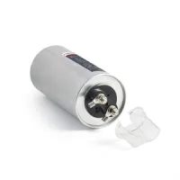
BGMJ 3YN capacitors provide a star-connected three-phase capacitor assembly with an accessible neutral. This allows phase-by-phase reactive compensation in an unbalanced network. The ratings below are phase-to-neutral voltages, and the output and capacitance columns describe the complete assembly.
| BGMJ model suffix | Phase-neutral voltage (kV) | Total output (kvar) | Total capacitance (µF) | Phase current (A) | ØD×H (mm) | Stud (mm) | Figure |
|---|---|---|---|---|---|---|---|
| 0.23-3-3YN | 0.23 | 3 | 181 | 4.3 | 96×135 | M16×25 | YF1 |
| 0.23-4-3YN | 4 | 241 | 5.8 | 106×135 | |||
| 0.23-5-3YN | 5 | 301 | 7.2 | 116×135 | |||
| 0.23-6-3YN | 6 | 361 | 8.7 | 96×180 | |||
| 0.23-7.5-3YN | 7.5 | 451 | 10.9 | ||||
| 0.23-10-3YN | 10 | 602 | 14.5 | 96×210 | |||
| 0.23-12-3YN | 12 | 722 | 17.4 | 96×240 | |||
| 0.23-14-3YN | 14 | 842 | 20.3 | 96×280 | |||
| 0.23-15-3YN | 15 | 903 | 21.7 | ||||
| 0.23-16-3YN | 16 | 963 | 23.2 | ||||
| 0.23-20-3YN | 20 | 1203 | 29.0 | 106×280 | |||
| 0.23-25-3YN | 25 | 1504 | 36.2 | 116×280 |
| BGMJ model suffix | Phase-neutral voltage (kV) | Total output (kvar) | Total capacitance (µF) | Phase current (A) | ØD×H (mm) | Stud (mm) | Figure |
|---|---|---|---|---|---|---|---|
| 0.25-3-3YN | 0.25 | 3 | 153 | 4.0 | 96×135 | M16×25 | YF1 |
| 0.25-4-3YN | 4 | 204 | 5.3 | 106×135 | |||
| 0.25-5-3YN | 5 | 255 | 6.7 | 116×135 | |||
| 0.25-6-3YN | 6 | 306 | 8.0 | 96×180 | |||
| 0.25-7.5-3YN | 7.5 | 382 | 10.0 | ||||
| 0.25-10-3YN | 10 | 509 | 13.3 | 96×210 | |||
| 0.25-12-3YN | 12 | 611 | 16.0 | 96×240 | |||
| 0.25-14-3YN | 14 | 713 | 18.7 | 96×280 | |||
| 0.25-15-3YN | 15 | 764 | 20.0 | ||||
| 0.25-16-3YN | 16 | 815 | 21.3 | ||||
| 0.25-20-3YN | 20 | 1019 | 26.7 | 106×280 | |||
| 0.25-25-3YN | 25 | 1273 | 33.3 | 116×280 |
| BGMJ model suffix | Phase-neutral voltage (kV) | Total output (kvar) | Total capacitance (µF) | Phase current (A) | ØD×H (mm) | Stud (mm) | Figure |
|---|---|---|---|---|---|---|---|
| 0.28-3-3YN | 0.28 | 3 | 122 | 3.6 | 96×135 | M16×25 | YF1 |
| 0.28-4-3YN | 4 | 162 | 4.8 | 106×135 | |||
| 0.28-5-3YN | 5 | 203 | 6.0 | 116×135 | |||
| 0.28-6-3YN | 6 | 244 | 7.1 | 96×180 | |||
| 0.28-7.5-3YN | 7.5 | 305 | 8.9 | ||||
| 0.28-10-3YN | 10 | 406 | 11.9 | 96×210 | |||
| 0.28-12-3YN | 12 | 487 | 14.3 | 96×240 | |||
| 0.28-14-3YN | 14 | 568 | 16.7 | 96×280 | |||
| 0.28-15-3YN | 15 | 609 | 17.9 | ||||
| 0.28-16-3YN | 16 | 650 | 19.0 | ||||
| 0.28-20-3YN | 20 | 812 | 23.8 | 106×280 | |||
| 0.28-25-3YN | 25 | 1015 | 29.8 | 116×280 |
All listed models use the YF1 reference and an M16×25mm base stud. The same drawing includes other cylindrical capacitor outlines for comparison; use the YF1 arrangement and the model-specific diameter and height for these 3YN units.

Assess harmonic content before installing a capacitor bank. Systems with substantial harmonics require a suitable capacitor/reactor arrangement to avoid resonance. Use switching equipment rated for capacitor duty, or a suitable inrush-limiting arrangement where applicable, and provide circuit protection for every capacitor step or standalone compensation unit.
Allow at least 1 minute after switching a capacitor off before reconnecting it, so the individual step can discharge. Select the complete model, phase voltage and switching arrangement together; these neutral-connected units are distinct from ordinary three-terminal three-phase capacitors.
