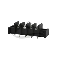
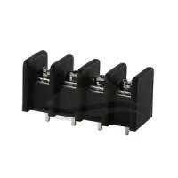


| Part Number: | ULO | - | TB41 | - | 55 | C | / | A | - | 02 | P | - | 3 | 1 | 0 | 0A |
|---|---|---|---|---|---|---|---|---|---|---|---|---|---|---|---|---|
| Explanation: |
Brand |
Series Code |
Model Family 55 - 10mm single-row barrier terminal block |
Tail Configuration C - Centered straight pins |
Mounting Ends A - Mounting ears |
Positions 02-24 - Two to twenty-four positions, written as two digits |
Position Unit P - Position-count suffix |
Color 1 - Grey |
Screw Head 1 - Cross-head screw in the illustrated ordering suffix |
Clamping 0 - Screw-down clamping in the illustrated ordering suffix |
Product Version 0A - Standard product |
The 55 series provides one row of screw connections at 10mm pitch, with 2-24 positions. C versions have centered straight pins, S versions have offset straight pins, H versions have extended eyelet lugs, and R versions have bent tails. /A bodies include mounting ears; /B bodies have compact ends without ears. The illustrated terminals are uncovered.
| Model | Tail style | Mounting ears | Overall body length, mm |
|---|---|---|---|
| ULO-TB41-55C/A | Centered straight pins | Yes | 10×(N+2) |
| ULO-TB41-55C/B | No | 10×N+2.38 | |
| ULO-TB41-55S/A | Offset straight pins | Yes | 10×(N+2) |
| ULO-TB41-55S/B | No | 10×N+2.38 | |
| ULO-TB41-55H/A | Extended eyelet lugs | Yes | 10×(N+2) |
| ULO-TB41-55H/B | No | 10×N+2.38 | |
| ULO-TB41-55R/A | Bent tails | Yes | 10×(N+2) |
| ULO-TB41-55R/B | No | 10×N+2.38 |
N denotes the number of positions, from 2 to 24. All bodies are 16.50mm deep and 18.50mm high, excluding tails. The central terminal section on /A versions is 10×N+2.38mm long.
All eight versions have a rated current of 32A. Select the voltage for the applicable overvoltage category and pollution degree. A value marked not specified is not an additional voltage rating.
| Models | III / pollution degree 3 | III / pollution degree 2 | II / pollution degree 2 | |||
|---|---|---|---|---|---|---|
| Rated voltage | Impulse voltage | Rated voltage | Impulse voltage | Rated voltage | Impulse voltage | |
| 55C/A, 55C/B, 55S/A, 55S/B | Not specified | 8kV | 320V | 8kV | Not specified | 8kV |
| 55H/A, 55R/A, 55R/B | 6kV | 6kV | 6kV | |||
| 55H/B | 320V | 600V | ||||
| Parameter | Use group B | Use group C | Use group D |
|---|---|---|---|
| Rated current | 20A | 10A | |
| Rated voltage | 300V | ||
| Wire range | 22-12AWG | ||
| Parameter | Value |
|---|---|
| Positions / rows / pitch | 2-24 / 1 / 10mm |
| Connection method | Screw connection |
| Solid conductor cross section | 0.5-4mm² |
| Flexible conductor cross section | 0.5-4mm² |
| Flexible conductor with ferrule | 0.5-4mm² |
| Clamping screw / tightening torque | M3.5 / 0.8N·m |
| Protection level | IP20 |
| Operating temperature | -40°C to 105°C |
| Housing / material group / flammability | PA66 / I / UL94V-0 |
| Contacts | Tin-plated copper alloy |
| Solder tails | Tin-plated brass |
| Screws | Nickel-plated steel |
| Environmental compliance | RoHS |
Dimensions in the table below are in millimetres. The first-to-last tail span is 10×(N-1)mm. /A mounting ears have Ø3.50mm holes with Ø5.50mm recesses. Use the model drawing for tail direction and the complete outline.
| Tail style | Section or width | Tail length or extension | Position and hole details |
|---|---|---|---|
| C | 1.5×0.8 | 5±0.3 | Centered pin row; PCB holes Ø2.2 |
| S | Pin row 4.05 from the near body edge; PCB holes Ø2.2 | ||
| H | 3.5×0.8 | 12.5±0.3 | Eyelet opening 2×2.5 |
| R | Shoulder width 3.5; tip width 1.5; thickness 0.8 | Horizontal extension 5±0.3; outside drop 5.3±0.3 | PCB holes Ø2.2 |


Specific tolerances beside dimensions take precedence. Values below are in millimetres.
| Dimension range | Total pitch tolerance | Nominal dimension tolerance |
|---|---|---|
| 0-30 | ±0.18 | ±0.20 |
| Over 30-53 | ±0.20 | ±0.25 |
| Over 53-70 | ±0.25 | ±0.30 |
| Over 70-90 | ±0.30 | ±0.35 |
| Over 90-115 | ±0.35 | ±0.44 |
| Over 115-150 | ±0.44 | ±0.55 |
| Over 150-200 | ±0.55 | ±0.70 |
| Over 200-250 | ±0.70 | ±0.80 |
| Over 250-320 | ±0.75 | ±0.90 |
| Geometric tolerance | Range or condition | Tolerance |
|---|---|---|
| Perpendicularity | Up to 10mm / over 10mm | 0.2mm / 0.3mm |
| Symmetry | All | 0.3mm |
| Straightness | Up to 100mm | 0.2mm |
| Parallelism | 100-150mm / over 150mm | 0.3mm / 0.5mm |
Use the order form ULO-TB41-55C/A-XXP-Y100A, replacing 55C/A with the required version, XX with 02-24 positions and Y with the color code. The illustrated 100A ending selects a cross-head screw, screw-down clamping and the standard 0A product configuration.
| Code | Color |
|---|---|
| 1 | Grey |
| 2 | Blue |
| 3 | Black |
| 4 | Green |
| 5 | Orange |
| 6 | Red |
| 7 | Transparent |
| 8 | Yellow |
| 9 | White |
