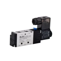
4V pneumatic solenoid valves offer five-port switching in two or three positions. Single-coil and double-coil 5/2 versions are available alongside double-coil 5/3 valves with closed, exhaust or pressure centre functions. Four body sizes cover M5 to 1/2″ nominal connections.
Control functions
Control code
Coils
Function
Selection detail
10
Single
5/2
Two-position switching
20
Double
5/2
Two-position switching with memory function
30C
Double
5/3
Closed centre
30E
Double
5/3
Exhaust centre
30P
Double
5/3
Pressure centre
Model selection
Body
Nominal port
5/2 models
5/3 models
Single coil
Double coil
Closed centre
Exhaust centre
Pressure centre
100
M5
4V110-M5
4V120-M5
4V130C-M5
4V130E-M5
4V130P-M5
1/8″
4V110-06
4V120-06
4V130C-06
4V130E-06
4V130P-06
200
1/8″
4V210-06
4V220-06
4V230C-06
4V230E-06
4V230P-06
1/4″
4V210-08
4V220-08
4V230C-08
4V230E-08
4V230P-08
300
1/4″
4V310-08
4V320-08
4V330C-08
4V330E-08
4V330P-08
3/8″
4V310-10
4V320-10
4V330C-10
4V330E-10
4V330P-10
400
1/2″
4V410-15
4V420-15
4V430C-15
4V430E-15
4V430P-15
Body codes 1, 2, 3 and 4 identify the 100, 200, 300 and 400 sizes. Port codes M5, 06, 08, 10 and 15 identify M5, 1/8″, 1/4″, 3/8″ and 1/2″ respectively. For example, 4V210-08 AC220V is a 200-size single-coil 5/2 valve with a 1/4″ nominal port and 220V AC coil.
Operating conditions
Parameter
Specification
Medium
Air filtered through a 40μm element
Pilot arrangement
Internal or external pilot
Operating pressure
0.15–0.8MPa
Proof pressure
1.2MPa
Ambient temperature
-20–70°C
Body
Aluminium alloy
Valve structure
Sliding spool
The proof rating is separate from the continuous operating-pressure range. Select the centre function to match the required actuator behaviour when neither coil is energised on a three-position valve.
Coil and connection options
Selection
Options
AC voltages
24V, 36V, 110V, 220V, 380V
DC voltages
12V, 24V, 36V, 110V
Electrical connection
Terminal plug or grommet lead-wire configuration
Each voltage requires its corresponding coil. The illustrated 4V210-08 selection graphic includes approximate product-envelope dimensions; use the model-specific mounting drawings below for installation.
Coil-voltage choices and approximate envelope of the pictured 4V210-08.
Valve construction
Sliding-spool and NBR seal arrangement.Pilot assembly and manual operating button on the illustrated configuration.Coil assembly and supply-port screen on the illustrated valve. Supply air must still meet the stated filtration requirement.
100-size installation dimensions
Linear dimensions below are in millimetres; threaded-port entries retain their thread designation. The 4V110 drawing table labels its final column B a second time; the final column gives the offset marked G on the end view.
Model
A thread
B
C
D
E
F
G offset
4V110-M5
M5×0.8
27
14.7
0
14
21.2
0
4V110-06
1/8″
28
14.2
1
16
20.2
3
4V120-M5
M5×0.8
27
57.7
0
14
64.3
0
4V120-06
1/8″
28
57.2
1
16
63.2
3
4V110 and 4V120 outlines and model-dependent dimensions.
Model outline
A thread
B
C
D
E
F
G
4V130-M5
M5×0.8
27
57.7
0
14
64.3
0
4V130-06
1/8″
28
57.2
1
16
63.2
3
4V130 three-position valve outline; specify C, E or P centre function in the full model code.
200-size installation dimensions
Model
A thread
B thread
C
D
E
4V210-06
1/8″
1/8″
18
22.7
0
4V210-08
1/8″
1/4″
21
21.2
3
4V220-06
1/8″
1/8″
18
76.4
0
4V220-08
1/8″
1/4″
21
74.9
3
4V210 and 4V220 outlines, including the different main and exhaust port sizes.
Model outline
A thread
B thread
C
D
E
4V230-06
1/8″
1/8″
18
76.4
0
4V230-08
1/8″
1/4″
21
74.9
3
4V230 three-position valve outline for C, E and P centre-function selection.
300-size installation dimensions
Model
A thread
B thread
C
D
E
4V310-08
1/4″
1/4″
22
29
0
4V310-10
1/4″
3/8″
24
28
4
4V320-08
1/4″
1/4″
22
83.9
0
4V320-10
1/4″
3/8″
24
82.9
4
4V310 and 4V320 mounting outlines and port dimensions.
Model outline
A thread
B thread
C
D
E
4V330-08
1/4″
1/4″
22
83.9
0
4V330-10
1/4″
3/8″
24
82.9
4
4V330 three-position valve outline for C, E and P centre-function selection.
400-size installation dimensions
The 400-size drawings show five 1/2″ connections and a 34mm body width. The two-position single-coil 4V410 is 168.4mm long; double-coil 4V420 is 222.8mm long. Terminal and grommet versions have different electrical-connection envelopes.
4V410 and 4V420 mounting drawings for the 1/2″ configurations.
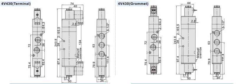
The three-position 4V430 outline has an overall length of 243.8mm. Select C, E or P to define its centre function.
4V430 three-position valve mounting outline, with dimensions in millimetres.