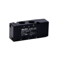
| Part Number: | 4A | 2 | 30C | - | 08 |
|---|---|---|---|---|---|
| Explanation: |
Series 4A - Air-piloted directional valve with five main ports |
Body Size 1 - 100 size; port M5 or 06 |
Pilot Control and Centre Function 10 - Single pilot; five ports, two positions |
Port Size M5 - M5; body size 1 |
4A valves use pneumatic pilot signals to switch five main ports. Two-position versions provide single-pilot or double-pilot control, while three-position versions offer closed, exhaust or pressure centre functions. The range covers 100 to 400 body sizes.
| Body size | Nominal port | Single-pilot model | Double-pilot model | Function | Operating pressure |
|---|---|---|---|---|---|
| 100 | M5 | 4A110-M5 | 4A120-M5 | 5/2 | 0.15–0.8MPa |
| 1/8″ | 4A110-06 | 4A120-06 | |||
| 200 | 1/8″ | 4A210-06 | 4A220-06 | ||
| 1/4″ | 4A210-08 | 4A220-08 | |||
| 300 | 1/4″ | 4A310-08 | 4A320-08 | ||
| 3/8″ | 4A310-10 | 4A320-10 | |||
| 400 | 1/2″ | 4A410-15 | 4A420-15 |
| Body size | Model stem | Nominal port | Control and function | Operating pressure |
|---|---|---|---|---|
| 100 | 4A130-M5 | M5 | Double pilot, 5/3 | 0.15–0.8MPa |
| 4A130-06 | 1/8″ | |||
| 200 | 4A230-06 | 1/8″ | ||
| 4A230-08 | 1/4″ | |||
| 300 | 4A330-08 | 1/4″ | ||
| 4A330-10 | 3/8″ | |||
| 400 | 4A430-10 | 3/8″ | ||
| 4A430-15 | 1/2″ |
Complete the three-position model with the centre-function code: C for closed centre, E for exhaust centre or P for pressure centre. For example, 4A230C-08 selects a closed-centre 200-size valve with a 1/4″ nominal main connection.
| Item | Options or identification |
|---|---|
| Switching method | Pneumatic pilot |
| Control code | 10: single pilot, two positions; 20: double pilot, two positions; 30C / 30E / 30P: double pilot, three positions |
| Body code | 1: 100; 2: 200; 3: 300; 4: 400 |
| Main port codes | M5: M5; 06: 1/8″; 08: 1/4″; 10: 3/8″; 15: 1/2″ |
| Thread options | G, PT or NPT for applicable threaded connections |
The main port markings are A and B for the working connections, P for supply, and R and S for exhaust. Pilot connections are separate from these five main ports.


| Drawing reference | 4A110-M5 | 4A110-06 |
|---|---|---|
| A, main port thread | M5×0.8 | PT1/8 |
| B | 27mm | 28mm |
| C | 14.6mm | 14.1mm |
| D | 0mm | 2mm |
| E | 30mm | 30mm |
| F | 13.1mm | 13.1mm |
| G | 0mm | 3mm |
The drawing shows five main ports of size A, a separate PT1/8 pilot connection, two 3.3mm mounting holes and an 18mm body width. Its dimensions apply to 4A110, not to the other body sizes or double-pilot configurations.

