


| Part Number: | ULO | - | TB42 | - | 46GS | / | B | - | 02 | P | - | 3 | 100A |
|---|---|---|---|---|---|---|---|---|---|---|---|---|---|
| Explanation: |
Code Prefix |
Series Number |
Structure 46S - S structure; this breakdown covers 46S/B only |
Body B - B body; the breakdown covers 46S/B, 46GS/B and 46R/B |
Positions 02–24 - 2–24 positions; retain two digits |
Position Unit |
Color 1 - Grey |
Customer Configuration 100A - Fixed tail for 46S/B and 46GS/B |
The 46 family uses a single row of screw connections at 9.5mm pitch with 2–24 positions. S/A provides end mounting flanges, S/B is a compact uncovered body, and GS/B adds a cover. R/B uses bent PCB tails and a different body outline. GR/B is a separate covered configuration; its final tail arrangement must be matched to the selected part.
| Model | Body configuration | PCB termination |
|---|---|---|
| TB42-46S/A | Uncovered, end flanges | Straight pins |
| TB42-46S/B | Uncovered, compact | |
| TB42-46GS/B | Covered, compact | |
| TB42-46R/B | Uncovered, bent-tail body | Right-angle pins |
| TB42-46GR/B | Covered configuration | Exact tail arrangement not established here |
| Models | IEC overvoltage category / pollution degree | Rated voltage | Rated current | Impulse voltage |
|---|---|---|---|---|
| 46S/A, 46S/B, 46GS/B, 46GR/B | III / 3 | Unspecified | Unspecified | 6kV |
| III / 2 | 250V | 24A | ||
| II / 2 | Unspecified | Unspecified | ||
| 46R/B | III / 3 | 600V | 32A | |
| III / 2 | ||||
| II / 2 | 1000V |
| Model | UL group B | UL group C | UL group D |
|---|---|---|---|
| 46S/A | 20A / 300V | 20A / 300V | 10A / 300V |
| 46S/B | |||
| 46GS/B | 20A / 150V | ||
| 46R/B | |||
| 46GR/B |
All models specify 22–12AWG conductors under UL data and 0.5–4mm² solid, flexible or ferruled flexible conductors under IEC data. The clamp specification is M4 with 1.2N·m tightening torque. Strip length and separate fixing-screw torque are unspecified.
| Property | Specification |
|---|---|
| Housing | PA66, insulation material group I, UL94V-0 |
| Protection | IP20 |
| Operating temperature | -40°C to +105°C |
| 46S/A and 46GR/B contacts | Tin-plated copper alloy |
| 46S/B clamp | Tin-plated phosphor bronze; separate block material and finish unspecified |
| 46GS/B solder pins and screws | Tin-plated brass pins; nickel-plated steel screws |
| 46GS/B cover | PC, UL94V-0 |
| 46R/B conductor and screws | Tin-plated brass conductor; zinc-plated steel screws |
| 46GR/B cover material | Unspecified |
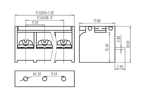
N is the number of positions. The first-to-last contact span is 9.5mm × (N−1). Use the exact model outline for the board pattern; cover and tail configurations change the mounting envelope.
| Model | Body length | Depth | Height reference | PCB opening |
|---|---|---|---|---|
| 46S/A | Overall 9.5mm × (N+2); central body 9.5mm × N + 1.3mm | 17.8mm | 15mm | Ø2.2mm |
| 46S/B | 9.5mm × N + 1.3mm | 18mm | ||
| 46GS/B | Overall length not assigned here | 17.8mm | 18mm covered; 15mm body | |
| 46R/B | 9.5mm × (N−1) + 10.9mm | 18mm | 15.6mm reference | 2.05×1.2mm slots |
| 46GR/B | 9.5mm × N + 1.3mm | 17.8mm | 18mm covered; 15mm body | Ø2.2mm in illustrated layout |
| Model | Tail section | Tail projection | Pin-line reference |
|---|---|---|---|
| 46S/A | 1.5×0.8mm | 7mm below body | 5mm from indicated body edge |
| 46S/B | 1.5±0.05 × 0.8±0.03mm | 5±0.3mm below body | 5mm edge offset; 5.4mm end margin |
| 46GS/B | 1.5×0.8mm | 4.8mm edge offset | |
| 46R/B | 1.4×0.7mm | 3.2±0.3mm lateral projection | 6.75mm indicated PCB reference |
| 46GR/B | 0.8mm thickness indicated; width unspecified | Not established | Use selected part configuration |


Specify TB42, the complete 46 structural suffix, the 02–24 position count, color and required customer configuration. Model-specific suffixes include Y100A for S/B and GS/B and Y000A for R/B, where Y denotes color.
| Field | Code meanings |
|---|---|
| Color | 1 grey; 2 blue; 3 black; 4 green; 5 orange; 6 red; 7 transparent; 8 yellow; 9 white |
| General screw-head option | 0 slotted; 1 cross-head |
| General screw-clamp position | 0 screw down; 1 screw up |
| Standard-product suffix | 0A |
