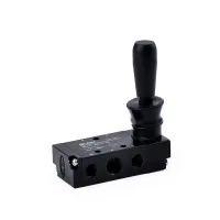
| Part Number: | 4H | 2 | 10 | - | 08 |
|---|---|---|---|---|---|
| Explanation: |
Valve Type 3H - 3/2-way hand lever valve |
Body Series 2 - 200 series; connection codes 06 or 08 |
Positions 10 - Two positions. |
Connection Size 06 - 1/8in; 200 series |
3H and 4H hand lever valves provide direct manual switching of compressed air. Choose 3H for a 3/2-way circuit or 4H for a 5/2-way circuit, then match the body size and connection code to the installation.
| Parameter | 200 series | 300 series | 400 series |
|---|---|---|---|
| Models | 3H210-06/08; 4H210-06/08 | 3H310-08/10; 4H310-08/10 | 3H410-10/15; 4H410-10/15 |
| Effective area | 16mm² | 25mm² | 30mm² |
| Cv | 0.89 | 1.4 | 1.68 |
| Largest listed port | 1/4in | 3/8in | 1/2in |
| Fluid | Air | ||
| Actuation | Direct acting, hand lever | ||
| Working pressure | 0–0.8MPa | ||
| Working temperature | 5–60°C | ||
| Lubrication | Not required | ||
| Operating angle | ±5° | ||
| Body material | Aluminum alloy | ||
| O-ring material | NBR | ||
Example: 4H210-08 identifies a 5/2-way hand lever valve, 200 series body, position code 10 and 1/4in connection.
| Code element | Selection |
|---|---|
| Valve type | 3H: 3/2-way; 4H: 5/2-way |
| Body series | 1: 100; 2: 200; 3: 300; 4: 400 |
| Position code | 10: two positions |
| Connection code | 06: 1/8in; 08: 1/4in; 10: 3/8in; 15: 1/2in |
Linear dimensions are in mm. Thread callouts R1, R2 and R3 correspond to the locations in the drawing.

| Model | ØD | A | B | C | E | F | J | R1 | R2 | R3 |
|---|---|---|---|---|---|---|---|---|---|---|
| 4H210-08 | 4 | 35 | 76.3 | 22 | 94.5 | 21 | 21 | R1/4 | R1/4 | R3/8 |
| 4H310-10 | 40 | 92 | 27 | 100 | 28 | 28 | R3/8 | R3/8 | ||
| 4H410-15 | 5.5 | 50 | 124 | 34 | 105 | 28.2 | 34.6 | R1/2 | R1/2 | R1/2 |
