


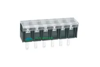


| Part Number: | ULO | - | TB43 | - | 38C | / | A | - | 02 | P | - | 3 | 100A |
|---|---|---|---|---|---|---|---|---|---|---|---|---|---|
| Explanation: |
Manufacturer ULO - ULO Electronics |
Series TB43 - 8.25mm covered barrier terminal blocks |
Terminal Type 38C - Centered straight PCB pins |
Mounting Ends A - With mounting ends |
Poles 02–24 - 2–24 poles, written with two digits |
Pole Unit P - Poles |
Color 1 - Grey |
Customer Code 100A - Fixed customer requirements code shown in the drawings |
The 38 series combines an 8.25mm barrier pitch with M3 screw connections and a clear cover. Each model has one row of 2–24 poles. C models have centered straight PCB pins; S models move the straight pin row toward one side; H models have extended solder lugs; R models have bent terminals. The A housing includes mounting ends, while the B housing has compact ends without mounting holes.
| Model | Terminal configuration | Housing ends | Pitch | Poles / connection rows |
|---|---|---|---|---|
| TB43-38C/A | Centered straight PCB pins | Mounting ends | 8.25mm | 2–24 / 1 |
| TB43-38C/B | Compact, no mounting holes | |||
| TB43-38S/A | Offset straight PCB pins | Mounting ends | ||
| TB43-38S/B | Compact, no mounting holes | |||
| TB43-38H/A | Extended solder lugs | Mounting ends | ||
| TB43-38H/B | Compact, no mounting holes | |||
| TB43-38R/A | Bent terminals | Mounting ends | ||
| TB43-38R/B | Compact, no mounting holes |
The following ratings apply to all eight models. Keep IEC conditions and UL use groups separate when selecting a terminal.
| IEC condition | Rated current | Rated voltage | Rated impulse voltage |
|---|---|---|---|
| Overvoltage category III, pollution degree 2 | 24A | 300V | 5kV |
| UL use group | Rated current | Rated voltage | Wire range |
|---|---|---|---|
| B | 15A | 300V | 22–14AWG |
| C | 150V | ||
| D | 10A | 300V |
| Connection parameter | Specification |
|---|---|
| Wire connection | Screw connection |
| Clamping screw | M3 |
| Clamping torque | 0.5N·m |
| Stripping length | 8mm |
| Solid, flexible and ferruled conductor cross sections in mm² | Not specified |
| Separate fixing screw and tightening torque | Not specified |
| Part or property | Specification |
|---|---|
| Housing | PA66, insulation material group I, UL94V-0 |
| Cover | PC, UL94V-2 |
| Contact and terminal material | Tin-plated copper alloy |
| Clamping screw material | Nickel-plated steel |
| Protection level | IP20 |
| Operating temperature | -40°C to +105°C |
| Substance compliance | RoHS compliance stated |
Specify the full terminal style and housing suffix, the pole count, color and screw configuration. In the example TB43-38C/A-XXP-Y100A, replace XX with the required pole count from 02 to 24 and Y with the color code. The general coding diagram shows the wider two-digit coding format; this series is specified for 2–24 poles.
| Code element | Meaning |
|---|---|
| TB43 | Series number |
| 38C/A, 38C/B, 38S/A, 38S/B, 38H/A, 38H/B, 38R/A or 38R/B | Terminal and housing configuration |
| XXP | Pole count, 02–24 |
| Y | 1 gray; 2 blue; 3 black; 4 green; 5 orange; 6 red; 7 transparent; 8 yellow; 9 white |
| Screw head digit | 0 slotted screw; 1 cross screw |
| Screw clamping digit | 0 screw down; 1 screw up |
| 0A | Standard product designation |
Dimensions below are in mm. N is the number of poles. All configurations have a 12mm body depth and a 17.30mm covered height, excluding the terminals. The 38R/B side view dimensions the cover depth at 14mm. A models have Ø3.20mm mounting holes with Ø5.40mm surrounding recesses. Use the model drawing to locate the terminals; the pin patterns differ even where the housing envelopes match.
| Housing | Overall length | Mounting hole centers | First-to-last terminal centers |
|---|---|---|---|
| 38C/A, 38S/A, 38H/A, 38R/A | 8.25 × (N + 2) | 8.25 × (N + 1) | 8.25 × (N − 1) |
| 38C/B, 38S/B, 38H/B, 38R/B | 8.25 × N + 3.18 | No mounting holes |
| Terminal style | Terminal width × thickness | Projection and position | PCB opening |
|---|---|---|---|
| 38C/A and 38C/B | 1 × 0.8 | 4 ±0.3 below the body; pin row 6 from the body edge | 1.56 × 1.36 |
| 38S/A and 38S/B | 4 ±0.3 below the body; pin row 2.75 from the nearer body edge | ||
| 38H/A and 38H/B | 3 × 0.8 | 8 ±0.3 below the body; lug row 6 from the body edge | 3.56 × 1.36 |
| 38R/A and 38R/B | 3 at the shoulder, 1.5 at the tip; 0.8 thick | 4 ±0.3 beyond the side face; vertical drop 3.70 as dimensioned in the side view | 2.06 × 1.36 |


Eight model-specific PDF drawings provide the terminal outlines, PCB layouts, ordering codes and technical notes. The tolerance ranges below apply where the drawings do not assign a specific tolerance.
| Dimension range in mm | Total pitch tolerance in mm | Nominal dimension tolerance in mm |
|---|---|---|
| Over 0 to 30 | ±0.18 | ±0.20 |
| Over 30 to 53 | ±0.20 | ±0.25 |
| Over 53 to 70 | ±0.25 | ±0.30 |
| Over 70 to 90 | ±0.30 | ±0.35 |
| Over 90 to 115 | ±0.35 | ±0.44 |
| Over 115 to 150 | ±0.44 | ±0.55 |
| Over 150 to 200 | ±0.55 | ±0.70 |
| Over 200 to 250 | ±0.70 | ±0.80 |
| Over 250 to 320 | ±0.75 | ±0.90 |
| Geometric tolerance | Applicable dimension range in mm | Tolerance in mm |
|---|---|---|
| Perpendicularity | 0–10 | 0.2 |
| Over 10 | 0.3 | |
| Symmetry | All | 0.3 |
| Straightness | Over 0 to 100 | 0.2 |
| Parallelism | Over 100 to 150 | 0.3 |
| Over 150 | 0.5 |
