


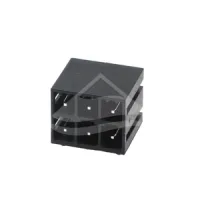
| Part Number: | ULO | - | TB22 | - | 2VH | / | 5.0 | - | 2x02 | P | - | 4 | 000A |
|---|---|---|---|---|---|---|---|---|---|---|---|---|---|
| Explanation: |
Brand ULO - Product brand |
Series Code TB22 - 5mm versions |
Model 2VH - Vertical, open-ended header |
Pitch 5.0 - 5mm; TB22 |
Positions 2x02-2x24 - Two rows of 2-24 contacts per row, 4-48 contacts in total; retain the 2x prefix and two-digit count per row |
Position Unit P - Contact positions |
Color 1 - Gray |
Product Version 000A - Standard product |
The 2VH and 2RH family provides two rows of mating pins for pluggable terminal connections. Select the pitch, mating direction and fixing arrangement together. Each row has 2–24 contacts, giving 4–48 contacts in total.
| Model | Series code | Pitch | Mating direction | Housing or fixing arrangement |
|---|---|---|---|---|
| 2VH/5.0 | TB22 | 5mm | Vertical | Open-ended header |
| 2VHM/5.0 | Fixing inserts at both ends of each row | |||
| 2RH/5.0 | Right angle | Open-ended header | ||
| 2RHM/5.0 | Fixing inserts at both ends of each row | |||
| 2VH/5.08 | TB28 | 5.08mm | Vertical | Open-ended header |
| 2VHM/5.08 | Fixing inserts at both ends of each row | |||
| 2RH/5.08 | Right angle | Open-ended header | ||
| 2RHM/5.08 | Fixing inserts at both ends of each row | |||
| 2RHC/5.08 | Enclosed, individually partitioned mating cavities |
| Models | Overvoltage category | Pollution degree | IEC current | Rated voltage | Impulse voltage |
|---|---|---|---|---|---|
| 2VH/5.0, 2VHM/5.0, 2RH/5.0 | III | 2 | 10A | 320V | 4kV |
| 2RHM/5.0 | 2.5kV | ||||
| 2VH/5.08, 2VHM/5.08, 2RH/5.08, 2RHM/5.08 | 4kV | ||||
| 2RHC/5.08 | 3 | 8A | 250V | ||
| 2 | 400V | ||||
| II | 630V |
| Models | UL use group B | UL use group C | UL use group D |
|---|---|---|---|
| 2VH, 2VHM, 2RH and 2RHM at both pitches | 15A, 300V | Not specified | 10A, 300V |
| 2RHC/5.08 | 10A, 300V |
| Component or property | 2VH, 2VHM, 2RH and 2RHM | 2RHC/5.08 |
|---|---|---|
| Housing | PA66, UL94V-0 | |
| Cover | PA66, UL94V-0 | Not separately specified |
| Insulation material group | I | |
| Contact pins | Tin-plated brass | Tin-plated copper alloy |
| Fixing nuts, where fitted | Brass | Not specified |
| Protection level | IP20 | |
| Operating temperature | -40°C to 105°C | |
| RoHS compliance | Specified | Not specified |
In the comparison tables, n means contacts per row. Each header has 2n contacts. All dimensions are in millimetres. The vertical models have a 22mm body height, 28.7mm transverse body dimension, 20mm PCB row spacing and 1mm-square pins. Their solder tails project 3.9±0.3mm; PCB holes are 1.7mm in diameter.
| Model | Body length | Pin span per row | Longitudinal end reference | Fixing-centre span along row | PCB transverse edge reference |
|---|---|---|---|---|---|
| 2VH/5.0 | 5(n−1)+7.08 | 5(n−1) | 3.5 | Not applicable | 3.9 |
| 2VHM/5.0 | 5(n+2) | 7.5 | 5(n+1) | ||
| 2VH/5.08 | 5.08(n−1)+7.08 | 5.08(n−1) | 3.54 | Not applicable | |
| 2VHM/5.08 | 5.08(n−1)+15.24 | 7.62 | 5.08(n−1)+10.16 |
The 5mm VHM drawing places a fixing centre 2.5mm from the body end, then the first contact 5mm farther in. The 5.08mm VHM drawing uses 2.54mm and 5.08mm respectively.


The RH and RHM models have a 22mm body depth, 28.7mm body height and 1mm-square pins. The PCB rows are 10mm apart, with a 2mm transverse edge reference. Pin projection is 3.5±0.3mm, and PCB holes are 1.6mm in diameter. These dimensions apply to the RH and RHM models listed below.
| Model | Body length | Pin span per row | Longitudinal end reference | Additional dimension |
|---|---|---|---|---|
| 2RH/5.0 | 5(n−1)+7 | 5(n−1) | 3.5 | 20mm between mating rows |
| 2RHM/5.0 | 5(n+2) | 7.5 in PCB layout | 5mm from fixing centre to first contact | |
| 2RH/5.08 | 5.08(n−1)+7.08 | 5.08(n−1) | 3.54 | 20mm between mating rows |
| 2RHM/5.08 | 5.08n+7.08 | 5.08mm from fixing centre to first contact | 20.24mm between fixing-centre rows |
The 10mm pin-row dimension has an individual ±0.3mm tolerance in the side views. In the RH and RHM drawings, N counts total contacts across both rows. The enclosed 2RHC/5.08 configuration has its own housing; the RH and RHM outline dimensions are not assigned to it.


These tolerances apply to the illustrated VH, VHM, RH and RHM models where no individual tolerance is shown. Ranges and deviations below are in millimetres.
| Dimension range | Total pitch tolerance | Nominal dimension tolerance |
|---|---|---|
| 0–30 | ±0.18 | ±0.20 |
| >30–53 | ±0.20 | ±0.25 |
| >53–70 | ±0.25 | ±0.30 |
| >70–90 | ±0.30 | ±0.35 |
| >90–115 | ±0.35 | ±0.44 |
| >115–150 | ±0.44 | ±0.55 |
| >150–200 | ±0.55 | ±0.70 |
| >200–250 | ±0.70 | ±0.80 |
| >250–320 | ±0.75 | ±0.90 |
| Geometric property | Range | Tolerance |
|---|---|---|
| Perpendicularity | Up to 10mm | 0.2mm |
| Over 10mm | 0.3mm | |
| Symmetry | All dimensions | 0.3mm |
| Straightness | Up to 100mm | 0.2mm |
| Parallelism | 100–150mm | 0.3mm |
| Over 150mm | 0.5mm |
Use TB22 for 5mm models and TB28 for 5.08mm models, followed by the full structural suffix. The VH, VHM, RH and RHM drawing codes use 2×XXP, where XX is 02–24 contacts per row, and the standard suffix Y000A. Y denotes housing colour. Choose the mating connector by its complete interface specification, including pitch, contact arrangement and fixing geometry.
| Colour code | Colour |
|---|---|
| 1 | Grey |
| 2 | Blue |
| 3 | Black |
| 4 | Green |
| 5 | Orange |
| 6 | Red |
| 7 | Transparent |
| 8 | Yellow |
| 9 | White |
