


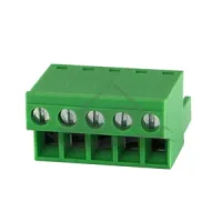


| Part Number: | ULO | - | TB23 | - | 2KAM | / | 5.0 | - | 02 | P | - | 4 | 0 | 0 | 0A |
|---|---|---|---|---|---|---|---|---|---|---|---|---|---|---|---|
| Explanation: |
Code Prefix |
Series and Code Scope TB21 - 5.0mm: factory 2K, 2KM or 2KF |
Factory Body Code 2K, 2KM - Base body or flanged base body on TB21/27/33/39; named KC body or flanged KC body on TB22/28/34 |
Pitch 5.0 - TB21, TB22 or TB23: 5.0mm |
Positions 02–24 - 2–24 positions; preserve two digits |
Count Suffix P - Position-count suffix |
Color 1 - Gray |
Screw Head 0 - Slotted |
Screw Clamping 0 - Screw down |
Configuration 0A - Standard product |
The 2K family provides single-row screw terminal plugs in 5.0mm, 5.08mm, 7.5mm, 7.62mm and 10.16mm pitches. Each listed model supports 2–24 positions. M suffixes identify flanged versions; KA, KB, KC, KF and KL bodies differ in wire entry, screw access and outline. Select the complete model, position count and matching interface. Similar pitch or appearance alone does not establish mating compatibility.
IEC values below apply to overvoltage category III and pollution degree 2, except the TB83 models, which specify III / 3. Other IEC condition combinations are not specified. Conductor ranges apply to solid, flexible and flexible conductors with ferrules as listed. UL AWG limits remain separate from metric wire ranges.
| Model | Pitch | IEC current / voltage / impulse | Conductor range | Strip length | UL group |
|---|---|---|---|---|---|
| TB21-2K/5.0 | 5.0mm | 20A / 320V / 2.5kV | 1–2.5mm² | 7mm | A |
| TB21-2KM/5.0 | 20A / 320V / 4kV | ||||
| TB23-2KA/5.0, TB23-2KAM/5.0, TB23-2KB/5.0, TB23-2KBM/5.0 | 18A / 320V / 4kV | ||||
| TB22-2KC/5.0, TB22-2KCM/5.0 | 20A / 320V / 4kV | 0.2–2.5mm² | 10mm | B | |
| TB21-2KF/5.0, TB21-2KFM/5.0 | 7–8mm | A | |||
| TB27-2K/5.08 | 5.08mm | 15A / 320V / 2.5kV | 1–2.5mm² | 7mm | |
| TB27-2KM/5.08 | 15A / 320V / 2kV | ||||
| TB29-2KA/5.08, TB29-2KAM/5.08, TB29-2KB/5.08, TB29-2KBM/5.08 | 18A / 320V / 4kV | ||||
| TB28-2KC/5.08 | 20A / 320V / 4kV | 0.2–2.5mm² | 10mm | C | |
| TB28-2KCM/5.08 | B | ||||
| TB27-2KL/5.08, TB27-2KLM/5.08 | 1–2.5mm² | D | |||
| TB41-2KA/7.62, TB41-2KAM/7.62, TB41-2KB/7.62 | 7.62mm | 18A / 400V / 4kV | 7mm | A | |
| TB41-2KBM/7.62 | 18A / 320V / 4kV | ||||
| TB40-2KC/7.62 | 20A / 400V / 6kV | 0.2–2.5mm² | 10mm | C | |
| TB40-2KCM/7.62 | 20A / 400V / 4kV | ||||
| TB83-2K/10.16, TB83-2KM/10.16 | 10.16mm | 57A / 600V / 6kV | 0.5–10mm² | 7–8mm | E |
| TB33-2K/7.5 | 7.5mm | 16A / 400V / 4kV | 1–2.5mm² | 7mm | A |
| TB33-2KM/7.5 | 7.5mm | ||||
| TB35-2KA/7.5, TB35-2KB/7.5 | 18A / 400V / 4kV | 7mm | |||
| TB35-2KAM/7.5 | 10A / 400V / 4kV | ||||
| TB35-2KBM/7.5 | 18A / 400V / 6kV | ||||
| TB34-2KC/7.5, TB34-2KCM/7.5 | 20A / 400V / 4kV | 0.2–2.5mm² | 10mm | C | |
| TB39-2K/7.62 | 7.62mm | 16A / 400V / 4kV | 1–2.5mm² | 7mm | A |
| TB39-2KM/7.62 | 20A / 400V / 4kV | 7.5mm |
| Table group | UL use group B | UL use group C | UL use group D | UL wire range |
|---|---|---|---|---|
| A | 15A / 300V | Not specified | 10A / 300V | 28–12AWG |
| B | 10A / 300V | 10A / 150V | 28–16AWG | |
| C | 28–12AWG | |||
| D | Not specified | 24–12AWG | ||
| E | 52A / 600V | 20–6AWG | ||
Letters A–E above are comparison keys, not product ordering suffixes. TB21-2KF/5.0 specifies a dielectric test of 2000VAC for 1 minute; this test value is not a continuous operating voltage.
| Models | Connection screw | Connection torque | Flange fixing |
|---|---|---|---|
| All models except the exceptions below | M3 | 0.5N·m | M versions: M2.5, 0.4N·m |
| TB22-2KC/5.0 | M2 shown in the component schedule | Not established for this M2 screw | None |
| TB27-2KL/5.08, TB27-2KLM/5.08 | M2.5 | 0.4N·m | KLM: M2.5, 0.4N·m |
| TB83-2K/10.16, TB83-2KM/10.16 | M4 | 1.2N·m | KM flange screw size and torque not specified |
| Property | Specification |
|---|---|
| Rows / positions | 1 row / 2–24 positions |
| Connection | Screw clamp |
| Protection level | IP20 |
| Operating temperature | -40°C to +105°C |
| Insulating housing and cover | PA66, material group I, UL94V-0 |
| Standard contact construction | Copper-alloy blocks and phosphor-bronze clamps; zinc-plated steel connection screws |
| Nickel-plated clamps | TB22-2KC and 2KCM; TB27-2K; TB29-2KBM; TB41-2KBM; TB40-2KCM; TB34-2KCM; TB39-2K |
| Other standard clamps | Tin-plated phosphor bronze, except the TB83 construction below |
| Standard block finish | Nickel-plated brass; TB28-2KC and TB34-2KC use zinc-plated brass |
| TB83 construction | Silver-plated copper clamp, stainless-steel spring and nickel-plated copper-alloy cage and M4 screw; KM also lists a tin-plated copper-alloy screw |
| Environmental declaration | RoHS compliance stated |
N denotes the number of positions. The contact span is 5.0 × (N−1)mm. Base K and KM bodies differ from the taller KA, KB and KC options; KF uses its own outline. Flange extensions must be included in enclosure clearance.


The contact span is 5.08 × (N−1)mm. KL and KLM have an angled wire-entry body and use M2.5 connection screws.


The two pitches are distinct. Use 7.5 × (N−1)mm or 7.62 × (N−1)mm for contact span as appropriate. Drawings showing only the active terminal body do not establish total flange width.


TB83 models use M4 connections for 0.5–10mm² conductors. Their 57A IEC rating and 52A UL B/C rating apply only to these models.


| Ordering field | Selection |
|---|---|
| Product | Exact TB model, body suffix and pitch |
| Positions | 02–24; the generic 02–99 legend does not extend these model ranges |
| Colour code | 1 grey; 2 blue; 3 black; 4 green; 5 orange; 6 red; 7 transparent; 8 yellow; 9 white |
| Screw head | 0 slotted; 1 cross-head |
| Clamping code | 0 screw down; 1 screw up |
| Standard suffix | 0A |
| Dimension range | Pitch tolerance | Nominal dimension tolerance |
|---|---|---|
| Over 0–30mm | ±0.18mm | ±0.20mm |
| Over 30–53mm | ±0.20mm | ±0.25mm |
| Over 53–70mm | ±0.25mm | ±0.30mm |
| Over 70–90mm | ±0.30mm | ±0.35mm |
| Over 90–115mm | ±0.35mm | ±0.44mm |
| Over 115–150mm | ±0.44mm | ±0.55mm |
| Over 150–200mm | ±0.55mm | ±0.70mm |
| Over 200–250mm | ±0.70mm | ±0.80mm |
| Over 250–320mm | ±0.75mm | ±0.90mm |
| Geometric tolerance | Range | Value |
|---|---|---|
| Perpendicularity | All stated dimensions | 0.2mm |
| Straightness | All stated dimensions | 0.2mm |
| Symmetry | 0–10mm / over 10mm | 0.2mm / 0.3mm |
| Parallelism | 0–100mm / over 100–150mm | 0.3mm / 0.5mm |
Apply an explicit dimension tolerance before the general tables. Match the mating projection, latch, flange centres and terminal orientation to the intended counterpart and enclosure.
