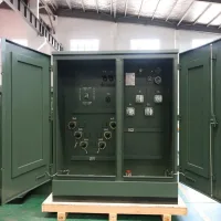
250 kVA Pad-Mounted Distribution Transformer is prepared for ground-level utility and industrial distribution. This series description presents the application, construction, protection, and specification details in finished product copy.
Key Advantages
For ground-level utility and industrial distribution, key Advantages is treated as a practical design and selection point rather than generic catalog wording.
Built for compact urban and light industrial networks, this 250 kVA pad-mounted transformer utilizes high-quality copper or aluminum windings and oil-immersed construction. Its three-phase design ensures stable voltage delivery, and the layout allows straightforward inspection and maintenance.
ZBW Series Prefabricated Box-Type Substation Overview
For ground-level utility and industrial distribution, zBW Series Prefabricated Box-Type Substation Overview is treated as a practical design and selection point rather than generic catalog wording.
The ZBW series prefabricated box-type substation (commonly referred to as the American-style box-type transformer) features a "product"-shaped structure. Its transformer and high/low-voltage equipment are closely integrated into a single unit. Among its design highlights, three sides of the transformer are exposed to the air-ensuring excellent heat dissipation-and the transformer can be separated from the enclosures of the high and low-voltage equipment, facilitating easy maintenance.
The 813 series oil-immersed transformer is equipped with a chip-type oil tank, requires no oil cushion, and adopts a fully enclosed design. Components such as high-voltage and low-voltage bushings, tap changers, oil level indicators, pressure relief valves, and oil drain valves are all installed on the end plate of the high-pressure chamber. This layout ensures reasonable component positioning, making it convenient for observation and operation.
The high-pressure chamber and low-pressure chamber are separated by steel plates. While the high-pressure chamber, low-pressure chamber, and transformer are relatively independent, they collectively form a complete, integrated box. This design results in a compact structure, small volume, and lightweight build. Additionally, power distribution switchgear is installed on both the high-voltage and low-voltage sides of the substation.
Use Environment
For ground-level utility and industrial distribution, use Environment is treated as a practical design and selection point rather than generic catalog wording.
The pad-mounted transformer must operate under the following environmental conditions to ensure stable performance and safe operation.
Cooling Condition Adopts air self-cooling mode, relying on natural air circulation to dissipate heat generated during transformer operation, which is suitable for its structural design and common application scenarios.
Wind speed: Equivalent to 34m/s (not more than 700 Pa).
Temperature Requirement The outdoor ambient temperature shall not be higher than 40℃ and not lower than -45℃. The monthly average temperature shall not exceed 30℃, and the annual average temperature shall not exceed 20℃. This limits the long-term temperature load on the transformer to avoid performance degradation caused by extreme temperature accumulation.
Altitude Requirement The installation altitude shall not exceed 1000m.
Humidity Requirement At a temperature of 25℃, the maximum relative humidity of the air shall not exceed 95%, and the daily average relative humidity shall not exceed 90%.
Product Characteristics
For ground-level utility and industrial distribution, product Characteristics is treated as a practical design and selection point rather than generic catalog wording.
Small size, compact structure, and easy installation: It can be used for both ring network and terminal applications, with reliable personal safety protection.
Low loss, low noise, and superior performance.
Anti-theft cabinet design: The cabinet adopts an anti-theft structure.
Low temperature rise and strong overload capacity.
Product Advantages
For ground-level utility and industrial distribution, product Advantages is treated as a practical design and selection point rather than generic catalog wording.
Compact structure and small size: It is only about 1/3 to 1/5 the size of domestic European-style boxes with the same capacity, greatly reducing the floor space. Fully sealed and fully insulated structure: This eliminates the need for insulation distances and provides reliable personal safety protection. Flexible high-voltage connection: It can be used for both ring network and terminal connections, offering flexible power supply modes and high reliability.
Excellent transformer performance: The transformer features low loss, low noise, low temperature rise, strong overload capacity, and excellent short-circuit impact resistance. Adaptable to low-voltage needs: It meets the requirements of various low-voltage power supply scenarios, and can either be selected based on existing plans or customized according to specific demands.
Versatile cable connections & supporting devices: Two types of cable connections are available-cable head plugs and 600A/200A elbow-type fixed cable joints. It can also be equipped with fully insulated zinc oxide arrester devices. Additionally, the 200A cable head supports live hot-swapping and functions as an isolating switch.
Applicable Standards
Applicable Standards summarizes the protection, safety, or standard-related details that matter during engineering selection.
This product complies with the following standards.
Main Technical Parameters.
Technical parameter.
10/0.4 (High/low voltage).
Maximum operating voltage.
12 (High voltage side).
Transformer Description
For ground-level utility and industrial distribution, transformer Description is treated as a practical design and selection point rather than generic catalog wording.
A new S9 series transformer body is selected, featuring low loss, good overload capacity, and strong short-circuit resistance; all fasteners are protected. Alternatively, the S11 series ring jointless core transformer (with better performance) can also be chosen. Transformer Selected new S9 series transformer body, low loss, good overload capacity, strong short-circuit resistance, all fasteners are protected. The S11 series ring jointless core transformer with better performance can also be selected.
Voltage KV - High tension.
Voltage KV - Low pressure.
No-load current % - S9.
No-load current % - S10.
No-load current % - S11.
Electrical and Mechanical Data
The table data is organized for quick rating comparison, project specification, and transformer selection.
Serial number
Item
Units
Technical parameter
1
Rated voltage
KV
10/0.4 (High/low voltage)
2
Maximum operating voltage
KV
12 (High voltage side)
3
Rated frequency
Hz
50
4
Rated capacity
KVA
150-1600
5
1min power frequency withstand voltage
KV
35
6
Lightning impulse voltage
KV
75
7
Cooling mode
Oil-immersed self-cooling
8
High voltage backup fuse breaking current
KA
50
9
Breaking current of plug-in fuse
KA
2.5
10
Ambient temperature
℃
35 ~ +40
11
Coil allowable temperature rise
K
65
12
No-load voltage regulation
±5% or ±2×2.5%
13
Noise level
DB
50
14
Protection class
IP43
Capacity (KVA)
Voltage KV - High tension
Voltage KV - Low pressure
Join group label
No-load current % - S9
No-load current % - S10
No-load current % - S11
No load loss W - S9
No load loss W - S10
No load loss W - S11
Impedance voltage %
Load loss
160
10±5% or 2×2.5%
0.4
Dyn11/Y,yno
1.4
0.2
400
320
255
4
2200
200
1.3
480
380
305
2600
250
1.2
560
450
360
3050
315
1.1
670
530
425
3650
400
1
0.15
800
650
505
4300
500
960
750
605
5100
630
0.9
1200
910
755
6200
800
0.8
1400
1080
980
4.5
7500
1000
0.7
1700
1260
10300
1250
0.6
1950
12000
S/N
Name
Unit
Technical Parameter
1
Rated Voltage
KV
10/0.4
2
High-voltage Side Rated Voltage
KV
10
3
Low-voltage Side Rated Voltage
KV
0.4
4
Maximum operating voltage (High voltage side)
KV
12
5
Rated Frequency
Hz
50
6
Rated Capacity
KVA
150-1600
7
High-voltage Switch Heat Stable Capacity
KA
20/26
8
Low-voltage Main Circuit Breaker Rated Short-circuit Breaking Capacity
KA
35
9
Low-voltage Distribution Circuit Breaker Rated Short-circuit Breaking Capacity
KA
35
10
High-voltage Load Switch Transfer Current
A
>1500
11
1 min Power Frequency Withstand Voltage
KV
35
12
Lightning Impulse Voltage
KV
75
13
Cooling Mode
Oil immersed self-cooling
14
High-voltage Backup Fuse Breaking Current
KA
50
15
Breaking Current of Plug-in Fuse
KA
2.5
16
Ambient Temperature
℃
35 ~ +40
17
Coil Allowable Temperature Rise
K
65
18
No-load Voltage Regulation
%
±5% or ±2 × 2.5%
19
Noise Level
DB
<50
20
Protection Grade of Box Shell
Not less than IP3X
Rated voltage(KV)
10
0.4
Transformer
Switch to ground and phase to phase
Between disconnectors
Power frequency withstand voltage (KV)
35
42
48
2.5
Peak value of impulse withstand voltage(KV)
75
85
–
Capacity KVA
Voltage KV
Join group label
No-load current %
No load loss W
Impedance voltage %
Load loss
High tension
Low pressure
S9
S10
S11
S9
S10
S11
160
10±5% or 2×2.5%
0.4
Dyn11 Yno
1.4
0.2
400
320
255
4.0
2200
200
1.3
480
380
305
2600
250
1.2
560
450
360
3050
315
1.1
670
530
425
3650
400
1.0
0.15
800
650
505
4300
500
960
750
605
5100
630
0.9
1200
910
755
6200
800
0.8
1400
1080
980
7500
1000
0.7
1700
1260
4.5
10300
1250
0.6
1950
12000
Item Name
Units
315A
630A
Rated voltage
KV
12
Maximum current
A
315
630
Rated frequency
Hz
50
Rated short-circuit closing current
KA
31.5
50
Rated short-time withstand current
KA
12.5
50
Rated short endurance time
S
2
Mechanical life
Second-rate
2000
Lightning impulse test
Phase to phase
KV
75
Isolation fracture
85
1min power frequency withstand voltage
Phase to phase
KA
42
Isolation fracture
48
Rated peak withstand current
KV
31.5
50
Capacity
A
B
C
H
Weight KG
200kVA and below
1830
1420
820
1850
< 2800
250-400kVA
1450
850
1980
3000-3300
500-630kVA
1480
880
2070
3600-3950
800kVA
2200
1700
950
2170
4500
Capacity
A
B
C
H
Weight KG
315kVA
2560
1600
600
1000
3050
400kVA
3270
500kVA
3400
630kVA
3900
800kVA
2760
800
4200
1000kVA
1950
4800
1250kVA
2910
5400
1600kVA
2200
1700
950
2170
4500
Product Detail Images
250 kVA Pad-Mounted Distribution Transformer enclosure, bushing, and cable compartment detail 1.250 kVA Pad-Mounted Distribution Transformer enclosure, bushing, and cable compartment detail 2.250 kVA Pad-Mounted Distribution Transformer enclosure, bushing, and cable compartment detail 3.250 kVA Pad-Mounted Distribution Transformer enclosure, bushing, and cable compartment detail 4.250 kVA Pad-Mounted Distribution Transformer enclosure, bushing, and cable compartment detail 5.250 kVA Pad-Mounted Distribution Transformer enclosure, bushing, and cable compartment detail 6.250 kVA Pad-Mounted Distribution Transformer enclosure, bushing, and cable compartment detail 7.250 kVA Pad-Mounted Distribution Transformer enclosure, bushing, and cable compartment detail 8.250 kVA Pad-Mounted Distribution Transformer enclosure, bushing, and cable compartment detail 9.250 kVA Pad-Mounted Distribution Transformer enclosure, bushing, and cable compartment detail 10.250 kVA Pad-Mounted Distribution Transformer enclosure, bushing, and cable compartment detail 11.250 kVA Pad-Mounted Distribution Transformer enclosure, bushing, and cable compartment detail 12.250 kVA Pad-Mounted Distribution Transformer enclosure, bushing, and cable compartment detail 13.250 kVA Pad-Mounted Distribution Transformer enclosure, bushing, and cable compartment detail 14.250 kVA Pad-Mounted Distribution Transformer enclosure, bushing, and cable compartment detail 15.250 kVA Pad-Mounted Distribution Transformer enclosure, bushing, and cable compartment detail 16.250 kVA Pad-Mounted Distribution Transformer enclosure, bushing, and cable compartment detail 17.250 kVA Pad-Mounted Distribution Transformer enclosure, bushing, and cable compartment detail 18.250 kVA Pad-Mounted Distribution Transformer enclosure, bushing, and cable compartment detail 19.250 kVA Pad-Mounted Distribution Transformer enclosure, bushing, and cable compartment detail 20.250 kVA Pad-Mounted Distribution Transformer enclosure, bushing, and cable compartment detail 21.