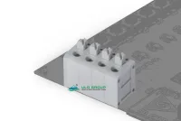

| Part Number: | ULO | - | TB12 | - | 211V | / | 5.0 | - | 02 | P | - | 4 | 000A |
|---|---|---|---|---|---|---|---|---|---|---|---|---|---|
| Explanation: |
Brand ULO - Product brand |
Series Code TB12 - 211 spring terminal block series |
Model 211V - Vertical conductor entry |
Pitch 5.0 - 5mm |
Positions 02-24 - 2-24 poles; use a two-digit code |
Position Unit P - Poles |
Color 1 - Gray |
Product Version 000A - Standard product |
211V/5.0 provides vertical wire entry and one PCB solder pin per pole. The 211R/5.0 version rotates the wire entry horizontally and uses two pins per pole. Both have push-button spring connections, a 5mm pitch and a single connection row with 2-24 poles.
| Model | Product reference | Wire entry | PCB pins per pole | Pitch | Poles |
|---|---|---|---|---|---|
| 211V/5.0 | ULO-TB12-211V/5.0 | Vertical | 1 | 5mm | 2-24 |
| 211R/5.0 | ULO-TB12-211R/5.0 | Horizontal | 2 |
| Applicable models | Condition | Current | Voltage | Impulse voltage |
|---|---|---|---|---|
| Both | IEC, overvoltage category III, pollution degree 2 | 15A | 250V | 2kV |
| IEC, category III / pollution degree 3; category II / pollution degree 2 | Not specified | Not specified | Not specified | |
| UL use group B | 8A | 300V | ||
| UL use groups C and D | Not specified | Not specified |
| Property | Both models |
|---|---|
| Solid conductor | 0.2-0.5mm² |
| Flexible conductor | 0.2-0.5mm² |
| Flexible conductor with ferrule | 0.2-0.5mm² |
| UL wire range | 24-20AWG |
| Stripping length | 8-9mm |
| Clamping screw and torque | Not applicable to the spring connection |
| Dimension | 211V/5.0 | 211R/5.0 |
|---|---|---|
| Housing length for N poles | (5 × N + 1.1)mm | |
| First-to-last pin span | 5 × (N−1) mm | |
| Indicated end-to-pin reference | 3mm | |
| Housing height excluding button projection | 12mm | 12.5mm |
| Overall height | 15.5mm reference | 12.5mm |
| Body depth | 12.5mm | 12mm |
| Overall depth including button projection | 12.5mm | 15.5mm reference |
| Solder tail length | 4±0.3mm | |
| Pin cross section | 0.9mm × 0.6mm | |
| PCB hole diameter | 1.3mm | |
| PCB pin-row spacing | Single row | 5mm |
| Pin-row edge reference | 6.25mm | 2.6mm |


| Component or property | Both models |
|---|---|
| Housing and cover | PA66, UL94V-0 |
| Insulation material group | I |
| Push button | POM, UL94HB |
| Spring | Stainless steel |
| Solder pins | Tin-plated copper alloy |
| Protection rating | IP20 |
| Operating temperature | -40°C to +105°C |
| Material compliance | RoHS |
| Field | Selection |
|---|---|
| Vertical-entry format | ULO-TB12-211V/5.0-XXP-Y000A |
| Horizontal-entry format | ULO-TB12-211R/5.0-XXP-Y000A |
| XX pole count | 02-24 |
| Y housing color | 1 gray; 2 blue; 3 black; 4 green; 5 orange; 6 red; 7 transparent; 8 yellow; 9 white |
| Standard suffix | 000A |
| Dimension range | Total pitch tolerance | Nominal dimension tolerance |
|---|---|---|
| 0-30mm | ±0.18mm | ±0.20mm |
| >30-53mm | ±0.20mm | ±0.25mm |
| >53-70mm | ±0.25mm | ±0.30mm |
| >70-90mm | ±0.30mm | ±0.35mm |
| >90-115mm | ±0.35mm | ±0.44mm |
| >115-150mm | ±0.44mm | ±0.55mm |
| >150-200mm | ±0.55mm | ±0.70mm |
| >200-250mm | ±0.70mm | ±0.80mm |
| >250-320mm | ±0.75mm | ±0.90mm |
| Geometric property | Range | Tolerance |
|---|---|---|
| Perpendicularity | Up to 10mm | 0.2mm |
| Over 10mm | 0.3mm | |
| Symmetry | All | 0.3mm |
| Straightness | Up to 100mm | 0.2mm |
| Parallelism | 100-150mm | 0.3mm |
| Over 150mm | 0.5mm |
