


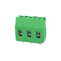
| Part Number: | ULO | - | TB25 | - | 129C | / | 5.0 | - | 02 | P | - | 4 | 000A |
|---|---|---|---|---|---|---|---|---|---|---|---|---|---|
| Explanation: |
Brand |
Series Code TB25 - 5.0mm pitch |
Model 129 - Straight solder pins; all four pitches |
Pitch 5.0 - TB25 |
Poles 02–24 - Two-digit count from 2 to 24 poles |
Pole Suffix |
Colour 1 - Grey |
Customer Requirements 000A - Standard suffix shown in the drawings |
These single-row PCB terminal blocks use rising-clamp screw connections. The 129 version has straight solder pins; 129C adds an insulating baseplate, while 129R uses bent solder pins for the alternate mounting orientation. Select the complete model, pitch and pole count.
| Pitch | Straight pins | Straight pins with baseplate | Bent pins | Pole count |
|---|---|---|---|---|
| 5.0mm | TB25-129/5.0 | TB25-129C/5.0 | TB25-129R/5.0 | 2-24 |
| 5.08mm | TB31-129/5.08 | TB31-129C/5.08 | TB31-129R/5.08 | |
| 7.5mm | TB37-129/7.5 | TB37-129C/7.5 | TB37-129R/7.5 | |
| 7.62mm | TB43-129/7.62 | TB43-129C/7.62 | TB43-129R/7.62 |
The following IEC values apply at overvoltage category III and pollution degree 2. Voltage and impulse ratings are specific to the listed models.
| Models | Current | Voltage | Impulse voltage |
|---|---|---|---|
| 129/5.0, 129C/5.0 | 20A | 250V | 4kV |
| 129R/5.0 | 320V | ||
| 129/5.08, 129R/5.08 | 250V | 2kV | |
| 129C/5.08 | 4kV | ||
| All 7.5mm and 7.62mm versions | 450V | 6kV |
| UL use group | Current | Voltage | Models |
|---|---|---|---|
| B | 20A | 300V | All versions |
| C | Not specified | Not specified | |
| D | 10A | 300V |
| Models | Metric wire range | UL wire range | Screw | IEC torque | UL torque | Strip length |
|---|---|---|---|---|---|---|
| 129/5.0, 129C/5.0 | 0.5-2.5mm² | 26-12AWG | M2.5 | 0.4N·m | 3.54lbf·in | 8mm |
| 129R/5.0 | 0.2-2.5mm² | 28-12AWG | 7-8mm | |||
| 129/5.08, 129C/5.08 | 0.5-2.5mm² | 26-12AWG | 8mm | |||
| 129R/5.08 | 0.2-2.5mm² | M3 | 0.5N·m | 4.43lbf·in | 7-8mm | |
| All 7.5mm and 7.62mm versions | 0.5-2.5mm² | 8mm |
The separately specified solid, flexible and flexible-with-ferrule conductor ranges are each 0.5-2.5mm² for every model. For 129R/5.0 and 129R/5.08, the wider 0.2-2.5mm² metric range has no conductor-class subdivision; it does not establish a 0.2mm² minimum for every conductor preparation.
| Property | Specification |
|---|---|
| Connection method | Rising-clamp screw connection |
| Connection rows | 1 |
| Separate fixing screw | None specified |
| Housing | PA66, insulation material group I, UL94V-0 |
| Solder pins | Tin-plated brass |
| Clamping conductor / cage | Nickel-plated brass |
| Screws | Zinc-plated steel |
| Protection level | IP20 |
| Operating temperature | -40°C to +105°C |
| Environmental compliance | RoHS |
Dimensions are in mm. N denotes pole count. Length along the pole row is pitch × N; the pin-row span is pitch × (N-1). Straight-pin versions specify a 1.00 × 0.80 pin section, Ø1.60 PCB holes and a 5.50 transverse row offset from the indicated reference edge.
| Model | Body depth | Body height | Solder-tail length | PCB end reference |
|---|---|---|---|---|
| 129/5.0 | 10.50 | 18.00 | 3.50±0.30 | 2.54 |
| 129C/5.0 | 18.00 above baseplate | 3.50±0.30 below baseplate | ||
| 129/5.08 | 11.20 | 18.00 | 5.00±0.30 | |
| 129C/5.08 | 10.50 | 19.50 including baseplate | 3.50±0.30 | |
| 129/7.5 | 11.20 | 18.00 | 3.75 | |
| 129C/7.5 | 19.50 including baseplate | |||
| 129/7.62 | 18.00 | 5.00±0.30 | 3.81 | |
| 129C/7.62 | 19.50 including baseplate | 3.50±0.30 |
The 5.0mm baseplate version dimensions its main housing separately from the baseplate. Follow the datum edges in each drawing when checking board clearance.


The 129R body profile includes an 18.00mm dimension along the screw axis. Its alternate mounting orientation places the 10.50mm or 11.20mm body dimension above the board. Bent-pin versions specify 1.00mm pin width and Ø1.60 PCB holes. The 5.0mm and 5.08mm versions also specify 0.80mm pin thickness. Length and pin-row span use the same pitch formulas as the straight versions.
| Model | Mounted body height | Pin projection | PCB end reference | Transverse pin-row reference |
|---|---|---|---|---|
| 129R/5.0 | 10.50 | 5.30±0.30 | 2.54 | 0.70 from near reference edge |
| 129R/5.08 | 11.20 | 5.00±0.30 | 17.30 from opposite reference edge | |
| 129R/7.5 | 10.50 | 5.30±0.30 | 3.75 | 0.70 from near reference edge |
| 129R/7.62 | 3.81 |
The 7.5mm outlines also identify a 0.60mm projecting side feature. Mounting references and body projections should be checked on the exact model drawing.


Choose the full model from the selection table, then specify the number of poles and colour. The suffix uses XXP for pole count and a colour/customer-requirement field in the form Y000A.
| Field | Selection |
|---|---|
| Prefix | TB25 for 5.0mm; TB31 for 5.08mm; TB37 for 7.5mm; TB43 for 7.62mm |
| Structure | 129 straight; 129C with baseplate; 129R bent pins |
| XXP | 2-24 poles |
| Y colour code | 1 grey; 2 blue; 3 black; 4 green; 5 orange; 6 red; 7 transparent; 8 yellow; 9 white |
| 000A | Customer requirement field |
The 129/7.62 ordering example uses colour code 4 for green; the same colour legend defines the other listed choices.
